
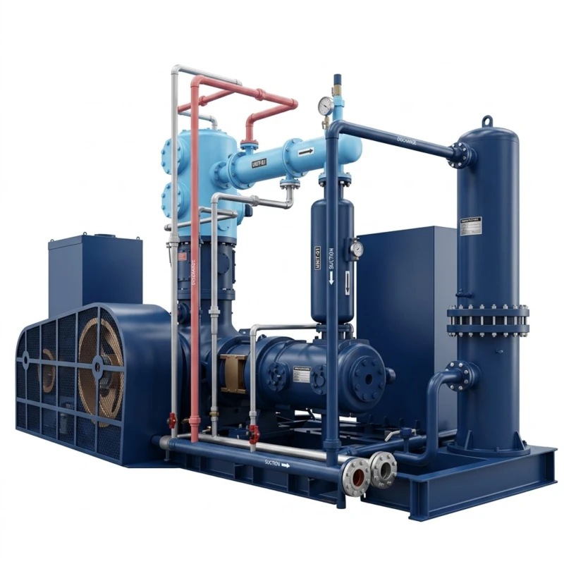
Oxygen and Nitrogen Compressor — Three-Series Oil-Free Reciprocating Piston Range
Series A: Oxygen Compressor 0.70–150 MPa · Series B: Nitrogen Compressor 0.40–150 MPa · Series C: Nitrogen Booster Compressor 0.40–40 MPa · Total 113 Standard Models · 5.5–3000 kW
The oxygen and nitrogen compressor series is an oil-free reciprocating piston compression system engineered specifically for the compression of pure oxygen (O₂), pure nitrogen (N₂), and mixed oxygen-nitrogen gas streams across the full pressure range from low-pressure distribution to ultrahigh-pressure cylinder filling and industrial process feed. These two gases represent opposite ends of the reactivity spectrum — oxygen is a powerful oxidiser that ignites hydrocarbon lubricants under pressure and concentration, while nitrogen is chemically inert but requires particular attention to oxygen displacement hazard and sealing integrity. Both require oil-free design using PTFE composite piston rings and dedicated distance-piece isolation, and both are produced in large quantities by cryogenic air separation units (ASUs) and pressure swing adsorption (PSA) plants whose output must be compressed for storage, pipeline distribution, or industrial process use.
The three-series range covers 113 standard models. Series A — Oxygen Compressor covers 30 models from 1 to 30 m³/min at discharge pressures of 0.70 to 150 MPa, serving medical oxygen, industrial oxygen, steel-making lance oxygen, and high-pressure oxygen cylinder filling. Series B — Nitrogen Compressor covers 49 models from 1 to 399 m³/min at discharge pressures of 0.40 to 150 MPa, serving chemical plant nitrogen blanketing, pipeline purging, high-pressure nitrogen cylinder filling, and nitrogen-atmosphere process applications. Series C — Nitrogen Booster Compressor covers 34 models receiving nitrogen at elevated inlet pressure (from PSA nitrogen generators or pipeline supply) and boosting to 0.40 to 40 MPa, with flow from 3 to 302 m³/min. All three series use PTFE oil-free piston rings, oxygen-compatible or nitrogen-service sealing materials, and explosion-proof or standard enclosed motors appropriate for each gas service.
Drive power spans 5.5 kW to 3,000 kW across the combined range, with voltage options of 380 V and 6–10 kV. Custom single-unit capacity within 5.5 kW to 3,000 kW available on request for all three series. All oxygen compressor models use oxygen-compatible PTFE piston rings, oxygen-rated stainless steel valve assemblies, and oxygen-safe lubricant-free cylinder designs with special degreasing and cleaning of all oxygen-wetted components prior to assembly.
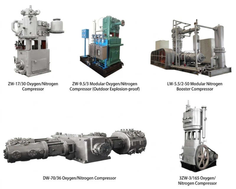
O₂ Service: 0.70–150 MPa
N₂ Service: 0.40–150 MPa
113 Standard Models
5.5–3000 kW
O₂-Compatible Materials
PSA Booster Variants
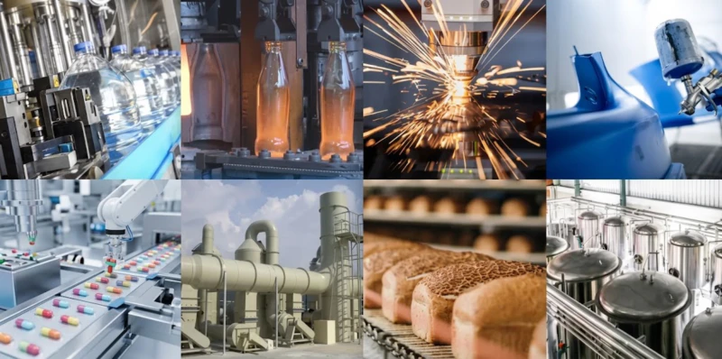
Typical applications: Medical oxygen compression for hospital pipeline supply and cylinder filling · Industrial oxygen for steel making basic oxygen furnace (BOF) lance · Glass furnace oxygen enrichment · Welding and cutting oxygen cylinder filling · Chemical and pharmaceutical oxygen feed · Nitrogen blanketing of flammable liquid storage · Pipeline purging and inerting · Tire inflation nitrogen systems · Heat treatment furnace nitrogen atmosphere · Nitrogen cylinder filling for industrial supply · PSA nitrogen generator output boosting · High-pressure nitrogen for gas-assisted injection moulding · Semiconductor process nitrogen
Series A — Oxygen Compressor
Oil-Free Reciprocating Oxygen Compressor · Discharge Pressure 0.70–150 MPa · Flow 1–30 m³/min · 30 Standard Models
All models use oxygen-compatible PTFE composite piston rings, oxygen-rated stainless steel or Monel valve assemblies, distance-piece crankcase isolation, and full degreasing and oxygen-service cleaning of all wetted components. Micro-positive-pressure inlet (near-atmospheric) from ASU liquid oxygen evaporator or PSA oxygen concentrator output. Custom capacity within 5.5–3,000 kW on request.
| No. | Model | Pattern | Flow (m³/min) | Discharge (MPa) | Dimensions L×W×H (mm) | Weight (t) | Power (kW) | Voltage (V) |
|---|---|---|---|---|---|---|---|---|
| 1 | ZW-1/7-A | Twin-col. two-stage | 1 | 0.70 | 720×763×1225 | 0.70 | 7.5 | 380 |
| 2 | ZW-3/7-A | Twin-col. two-stage | 3 | 0.70 | 720×763×1470 | 0.80 | 15 | 380 |
| 3 | LW-3/7-A | Twin-col. two-stage | 3 | 0.70 | 1520×800×1360 | 1.00 | 15 | 380 |
| 4 | LW-3/40-A | Twin-col. 3-stage | 3 | 4.00 | 2350×1296×2200 | 2.50 | 55 | 380 |
| 5 | LW-6/5-A | Twin-col. two-stage | 6 | 0.50 | 2250×1296×2200 | 2.00 | 30 | 380 |
| 6 | LW-6/7-A | Twin-col. two-stage | 6 | 0.70 | 2250×1296×2200 | 2.10 | 45 | 380 |
| 7 | LW-6/14-A | Twin-col. 3-stage | 6 | 1.40 | 2350×1296×2200 | 2.20 | 55 | 380 |
| 8 | LW-8/14-A | Twin-col. 3-stage | 8 | 1.40 | 2350×1296×2200 | 2.20 | 75 | 380 |
| 9 | LW-9/4-A | Twin-col. two-stage | 9 | 0.40 | 2350×1296×2200 | 2.00 | 45 | 380 |
| 10 | LW-10/7-A | Twin-col. two-stage | 10 | 0.70 | 2630×1550×2330 | 3.00 | 75 | 380 |
| 11 | LW-10/14-A | Twin-col. 3-stage | 10 | 1.40 | 2764×2000×3277 | 5.00 | 110 | 380 |
| 12 | LW-13/14-A | Twin-col. 3-stage | 13 | 1.40 | 2764×2000×3277 | 5.00 | 132 | 380 |
| 13 | LW-15/7-A | Twin-col. two-stage | 15 | 0.70 | 2630×1550×2330 | 3.00 | 110 | 380 |
| 14 | LW-15/14-A | Twin-col. 3-stage | 15 | 1.40 | 2764×2000×3277 | 5.00 | 160 | 380 |
| 15 | LW-15/150-A | Twin-col. 4-stage | 15 | 15.00 | 3500×2600×1850 | 9.00 | 350 | 380/6K/10K |
| 16 | LW-17/14-A | Twin-col. 3-stage | 17 | 1.40 | 2764×2000×3277 | 5.50 | 185 | 380 |
| 17 | LW-20/7-A | Twin-col. two-stage | 20 | 0.70 | 2630×1550×2330 | 3.00 | 132 | 380 |
| 18 | LW-20/14-A | Twin-col. 3-stage | 20 | 1.40 | 3500×1600×1850 | 9.00 | 250 | 380/6K/10K |
| 19 | LW-20/150-A | Twin-col. 4-stage | 20 | 15.00 | 3500×2600×1850 | 9.00 | 315 | 380/6K/10K |
| 20 | LW-22/150-A | Twin-col. 4-stage | 22 | 15.00 | 3500×2600×1850 | 9.00 | 315 | 380/6K/10K |
| 21 | LW-25/7-A | Twin-col. two-stage | 25 | 0.70 | 2926×1550×2690 | 3.20 | 160 | 380 |
| 22 | LW-25/14-A | Twin-col. 3-stage | 25 | 1.40 | 3500×1600×1850 | 9.00 | 315 | 380/6K/10K |
| 23 | LW-25/150-A | Twin-col. 4-stage | 25 | 15.00 | 3500×2600×1850 | 10.00 | 350 | 380/6K/10K |
| 24 | DW-25/14-A | Twin-col. 3-stage | 25 | 1.40 | 5456×3518×2535 | 13.00 | 315 | 380/6K/10K |
| 25 | DW-25/150-A | Twin-col. 4-stage | 25 | 15.00 | 5456×3518×2535 | 14.00 | 400 | 380/6K/10K |
| 26 | DW-28/150-A | Twin-col. 4-stage | 28 | 15.00 | 5456×3518×2535 | 14.00 | 450 | 380/6K/10K |
| 27 | DW-30/7-A | Twin-col. two-stage | 30 | 0.70 | 5456×3518×2535 | 13.00 | 250 | 380/6K/10K |
| 28 | DW-30/14-A | Twin-col. 3-stage | 30 | 1.40 | 5456×3518×2535 | 13.50 | 355 | 380/6K/10K |
| 29 | DW-30/40-A | Twin-col. 4-stage | 30 | 4.00 | 5456×3518×2535 | 14.00 | 450 | 380/6K/10K |
| 30 | DW-30/150-A | Twin-col. 4-stage | 30 | 15.00 | 5456×3518×2535 | 14.00 | 500 | 380/6K/10K |
Note: “-A” suffix denotes oxygen compressor service. All oxygen wetted components degreased and oxygen-service cleaned per oxygen safety standards before assembly. Custom capacity 5.5–3,000 kW on request.
Series B — Nitrogen Compressor
Oil-Free Reciprocating Nitrogen Compressor · Discharge Pressure 0.40–150 MPa · Flow 1–399 m³/min · 49 Standard Models
All models use PTFE oil-free piston rings with nitrogen-service sealing materials. Micro-positive-pressure inlet (near-atmospheric) from ASU nitrogen output or PSA nitrogen generator. Covers the complete range from small 5.5 kW nitrogen blanketing supply units to large 3,000 kW high-flow industrial nitrogen compressors. Custom capacity within 5.5–3,000 kW on request.
| No. | Model | Pattern | Flow (m³/min) | Discharge (MPa) | Dimensions L×W×H (mm) | Weight (t) | Power (kW) | Voltage (V) |
|---|---|---|---|---|---|---|---|---|
| 1 | ZW-1/4-N | Twin-col. single-stage | 1 | 0.40 | 720×763×1225 | 0.60 | 5.5 | 380 |
| 2 | ZW-3/7-N | Twin-col. single-stage | 3 | 0.70 | 720×763×1470 | 0.80 | 15 | 380 |
| 3 | ZW-3/14-N | Twin-col. two-stage | 3 | 1.40 | 720×763×1470 | 0.90 | 18.5 | 380 |
| 4 | ZW-5/7-N | Twin-col. single-stage | 5 | 0.70 | 1520×800×1360 | 0.70 | 22 | 380 |
| 5 | ZW-6/7-N | Twin-col. single-stage | 6 | 0.70 | 1520×800×1360 | 0.80 | 30 | 380 |
| 6 | ZW-6/14-N | Twin-col. two-stage | 6 | 1.40 | 1520×800×1360 | 0.90 | 37 | 380 |
| 7 | LW-6/7-N | Twin-col. single-stage | 6 | 0.70 | 2250×1296×2200 | 2.10 | 30 | 380 |
| 8 | LW-6/40-N | Twin-col. 3-stage | 6 | 4.00 | 2350×1296×2200 | 2.50 | 55 | 380 |
| 9 | LW-8/40-N | Twin-col. 3-stage | 8 | 4.00 | 2350×1296×2200 | 2.50 | 75 | 380 |
| 10 | LW-10/7-N | Twin-col. single-stage | 10 | 0.70 | 2630×1550×2330 | 3.00 | 55 | 380 |
| 11 | LW-10/14-N | Twin-col. two-stage | 10 | 1.40 | 2630×1550×2330 | 3.10 | 75 | 380 |
| 12 | LW-10/40-N | Twin-col. 3-stage | 10 | 4.00 | 2764×2000×3277 | 5.00 | 132 | 380 |
| 13 | LW-10/150-N | Twin-col. 4-stage | 10 | 15.00 | 2764×2000×3277 | 6.00 | 160 | 380 |
| 14 | LW-15/7-N | Twin-col. single-stage | 15 | 0.70 | 2630×1550×2330 | 3.00 | 75 | 380 |
| 15 | LW-15/14-N | Twin-col. two-stage | 15 | 1.40 | 2630×1550×2330 | 3.40 | 110 | 380 |
| 16 | LW-15/40-N | Twin-col. 3-stage | 15 | 4.00 | 2764×2000×3277 | 5.50 | 185 | 380 |
| 17 | LW-15/150-N | Twin-col. 4-stage | 15 | 15.00 | 3500×2600×1850 | 9.00 | 200 | 380/6K/10K |
| 18 | LW-20/7-N | Twin-col. single-stage | 20 | 0.70 | 2630×1550×2330 | 3.00 | 90 | 380 |
| 19 | LW-20/14-N | Twin-col. two-stage | 20 | 1.40 | 2630×1550×2330 | 3.20 | 132 | 380 |
| 20 | LW-20/40-N | Twin-col. 3-stage | 20 | 4.00 | 2764×2000×3277 | 6.00 | 250 | 380/6K/10K |
| 21 | LW-20/150-N | Twin-col. 4-stage | 20 | 15.00 | 3500×2600×1850 | 9.00 | 250 | 380/6K/10K |
| 22 | LW-25/7-N | Twin-col. single-stage | 25 | 0.70 | 2926×1550×2690 | 3.20 | 110 | 380 |
| 23 | LW-25/14-N | Twin-col. two-stage | 25 | 1.40 | 2926×1550×2690 | 3.50 | 160 | 380 |
| 24 | LW-25/40-N | Twin-col. 3-stage | 25 | 4.00 | 2764×2000×3277 | 6.50 | 315 | 380/6K/10K |
| 25 | LW-25/150-N | Twin-col. 4-stage | 25 | 15.00 | 3500×2600×1850 | 9.50 | 315 | 380/6K/10K |
| 26 | DW-30/7-N | Twin-col. single-stage | 30 | 0.70 | 5456×3518×2535 | 13.00 | 200 | 380/6K/10K |
| 27 | DW-30/14-N | Twin-col. two-stage | 30 | 1.40 | 5456×3518×2535 | 13.50 | 250 | 380/6K/10K |
| 28 | DW-30/40-N | Twin-col. 3-stage | 30 | 4.00 | 5456×3518×2535 | 14.00 | 355 | 380/6K/10K |
| 29 | DW-30/150-N | Twin-col. 4-stage | 30 | 15.00 | 5456×3518×2535 | 14.00 | 400 | 380/6K/10K |
| 30 | DW-40/7-N | Twin-col. single-stage | 40 | 0.70 | 5456×3518×2535 | 13.50 | 250 | 380/6K/10K |
| 31 | DW-40/14-N | Twin-col. two-stage | 40 | 1.40 | 5456×3518×2535 | 14.00 | 315 | 380/6K/10K |
| 32 | DW-40/40-N | Twin-col. 3-stage | 40 | 4.00 | 5456×3518×2535 | 14.50 | 450 | 380/6K/10K |
| 33 | DW-40/150-N | Twin-col. 4-stage | 40 | 15.00 | 5600×3640×3000 | 18.00 | 500 | 380/6K/10K |
| 34 | DW-50/7-N | Twin-col. single-stage | 50 | 0.70 | 5600×3640×3000 | 17.00 | 315 | 6K/10K |
| 35 | DW-50/14-N | Twin-col. two-stage | 50 | 1.40 | 5600×3640×3000 | 18.00 | 400 | 6K/10K |
| 36 | DW-50/40-N | Twin-col. 3-stage | 50 | 4.00 | 6000×3640×3000 | 18.00 | 500 | 6K/10K |
| 37 | DW-50/150-N | Twin-col. 4-stage | 50 | 15.00 | 6250×2100×2735 | 15.00 | 630 | 6K/10K |
| 38 | DW-60/7-N | Twin-col. single-stage | 60 | 0.70 | 6000×3640×3000 | 18.00 | 400 | 6K/10K |
| 39 | DW-60/14-N | Twin-col. two-stage | 60 | 1.40 | 6000×3640×3000 | 18.00 | 500 | 6K/10K |
| 40 | DW-60/40-N | Twin-col. 3-stage | 60 | 4.00 | 6250×2100×2735 | 15.00 | 630 | 6K/10K |
| 41 | DW-80/7-N | Twin-col. single-stage | 80 | 0.70 | 6250×2100×2735 | 15.00 | 500 | 6K/10K |
| 42 | DW-80/14-N | Twin-col. two-stage | 80 | 1.40 | 6250×2100×2735 | 15.00 | 630 | 6K/10K |
| 43 | DW-100/7-N | Twin-col. single-stage | 100 | 0.70 | 7200×3505×2820 | 27.00 | 630 | 6K/10K |
| 44 | DW-100/14-N | Twin-col. two-stage | 100 | 1.40 | 7200×3505×2820 | 28.00 | 800 | 6K/10K |
| 45 | DW-150/7-N | Twin-col. single-stage | 150 | 0.70 | 7200×3505×2820 | 28.00 | 900 | 6K/10K |
| 46 | DW-200/7-N | Twin-col. single-stage | 200 | 0.70 | 8000×4200×3100 | 40.00 | 1400 | 6K/10K |
| 47 | DW-250/7-N | Twin-col. single-stage | 250 | 0.70 | 8000×4200×3100 | 40.00 | 1600 | 6K/10K |
| 48 | DW-300/7-N | Twin-col. single-stage | 300 | 0.70 | 8000×4200×3100 | 45.00 | 2000 | 6K/10K |
| 49 | DW-399/7-N | Twin-col. single-stage | 399 | 0.70 | 8000×4200×3100 | 50.00 | 3000 | 6K/10K |
Note: “-N” suffix denotes nitrogen compressor service. Suffix /4, /7, /14, /40, /150 indicates discharge pressure in bar gauge (0.4, 0.7, 1.4, 4.0, 15.0 MPa respectively). Custom capacity 5.5–3,000 kW on request.
Series C — Nitrogen Booster Compressor (PSA Output and Pipeline Booster)
Nitrogen Booster Compressor Receiving Elevated Inlet Pressure from PSA Generators or Pipelines · Discharge Pressure 0.40–40 MPa · Flow 3–302 m³/min · 34 Standard Models
All Series C models receive nitrogen at elevated inlet pressure from an upstream PSA nitrogen generator or nitrogen pipeline supply and boost to higher process pressures. Multi-stage configurations (twin-column two-stage through four-column multi-stage) are matched to the overall pressure ratio from the specific inlet pressure to the required discharge pressure. PTFE oil-free piston rings and nitrogen-service sealing materials throughout. Custom capacity 5.5–3,000 kW on request.
| No. | Model | Pattern | Flow (m³/min) | Inlet Condition | Discharge (MPa) | Dimensions L×W×H (mm) | Weight (t) | Power (kW) | Voltage (V) |
|---|---|---|---|---|---|---|---|---|---|
| 1 | ZW-3/4~40 | Twin-col. two-stage | 3 | Inlet 0.40 MPa | 4.00 | 1550×985×2013 | 1.50 | 22 | 380 |
| 2 | ZW-3.5/4~40 | Twin-col. two-stage | 3.5 | Inlet 0.40 MPa | 4.00 | 1550×985×2013 | 1.50 | 30 | 380 |
| 3 | ZW-3/4~200 | Twin-col. 3-stage | 3 | Inlet 0.40 MPa | 20.00 | 1920×1900×2825 | 3.50 | 45 | 380 |
| 4 | ZW-6/4~40 | Twin-col. two-stage | 6 | Inlet 0.40 MPa | 4.00 | 1920×1900×2825 | 3.50 | 45 | 380 |
| 5 | ZW-6/4~200 | Twin-col. 3-stage | 6 | Inlet 0.40 MPa | 20.00 | 1920×1900×2825 | 3.50 | 75 | 380 |
| 6 | LW-6/4~40 | Twin-col. two-stage | 6 | Inlet 0.40 MPa | 4.00 | 2250×1296×2200 | 2.50 | 55 | 380 |
| 7 | LW-10/4~40 | Twin-col. two-stage | 10 | Inlet 0.40 MPa | 4.00 | 2630×1550×2330 | 3.20 | 75 | 380 |
| 8 | LW-10/4~200 | Twin-col. 3-stage | 10 | Inlet 0.40 MPa | 20.00 | 2764×2000×3277 | 5.50 | 132 | 380 |
| 9 | LW-10/4~400 | Twin-col. 4-stage | 10 | Inlet 0.40 MPa | 40.00 | 3500×2600×1850 | 9.00 | 200 | 380/6K/10K |
| 10 | LW-15/4~40 | Twin-col. two-stage | 15 | Inlet 0.40 MPa | 4.00 | 2630×1550×2330 | 3.50 | 110 | 380 |
| 11 | LW-15/4~200 | Twin-col. 3-stage | 15 | Inlet 0.40 MPa | 20.00 | 2764×2000×3277 | 6.00 | 185 | 380 |
| 12 | LW-15/4~400 | Twin-col. 4-stage | 15 | Inlet 0.40 MPa | 40.00 | 3500×2600×1850 | 9.50 | 250 | 380/6K/10K |
| 13 | LW-20/4~40 | Twin-col. two-stage | 20 | Inlet 0.40 MPa | 4.00 | 2764×2000×3277 | 5.50 | 132 | 380 |
| 14 | LW-20/4~200 | Twin-col. 3-stage | 20 | Inlet 0.40 MPa | 20.00 | 3500×1600×1850 | 9.00 | 250 | 380/6K/10K |
| 15 | LW-20/4~400 | Twin-col. 4-stage | 20 | Inlet 0.40 MPa | 40.00 | 3500×2600×1850 | 10.00 | 315 | 380/6K/10K |
| 16 | LW-25/4~40 | Twin-col. two-stage | 25 | Inlet 0.40 MPa | 4.00 | 2764×2000×3277 | 6.00 | 160 | 380 |
| 17 | LW-25/4~200 | Twin-col. 3-stage | 25 | Inlet 0.40 MPa | 20.00 | 3500×1600×1850 | 9.50 | 315 | 380/6K/10K |
| 18 | LW-25/4~400 | Twin-col. 4-stage | 25 | Inlet 0.40 MPa | 40.00 | 3500×2600×1850 | 11.00 | 400 | 380/6K/10K |
| 19 | DW-30/4~40 | Twin-col. two-stage | 30 | Inlet 0.40 MPa | 4.00 | 5456×3518×2535 | 13.00 | 200 | 380/6K/10K |
| 20 | DW-30/4~200 | Twin-col. 3-stage | 30 | Inlet 0.40 MPa | 20.00 | 5456×3518×2535 | 14.00 | 355 | 380/6K/10K |
| 21 | DW-30/4~400 | Twin-col. 4-stage | 30 | Inlet 0.40 MPa | 40.00 | 5456×3518×2535 | 14.50 | 450 | 380/6K/10K |
| 22 | DW-50/4~40 | Twin-col. two-stage | 50 | Inlet 0.40 MPa | 4.00 | 5600×3640×3000 | 17.00 | 315 | 6K/10K |
| 23 | DW-50/4~200 | Twin-col. 3-stage | 50 | Inlet 0.40 MPa | 20.00 | 6000×3640×3000 | 18.00 | 500 | 6K/10K |
| 24 | DW-50/4~400 | Twin-col. 4-stage | 50 | Inlet 0.40 MPa | 40.00 | 6000×3640×3000 | 19.00 | 630 | 6K/10K |
| 25 | DW-60/4~40 | Twin-col. two-stage | 60 | Inlet 0.40 MPa | 4.00 | 6250×2100×2735 | 15.00 | 400 | 6K/10K |
| 26 | DW-60/4~200 | Twin-col. 3-stage | 60 | Inlet 0.40 MPa | 20.00 | 6250×2100×2735 | 15.50 | 500 | 6K/10K |
| 27 | DW-60/4~400 | Twin-col. 4-stage | 60 | Inlet 0.40 MPa | 40.00 | 6250×2100×2735 | 16.00 | 630 | 6K/10K |
| 28 | DW-80/4~40 | Twin-col. two-stage | 80 | Inlet 0.40 MPa | 4.00 | 6250×2100×2735 | 15.00 | 500 | 6K/10K |
| 29 | DW-80/4~200 | Twin-col. 3-stage | 80 | Inlet 0.40 MPa | 20.00 | 7200×3505×2820 | 27.00 | 800 | 6K/10K |
| 30 | DW-100/4~40 | Twin-col. two-stage | 100 | Inlet 0.40 MPa | 4.00 | 7200×3505×2820 | 27.00 | 630 | 6K/10K |
| 31 | DW-100/4~200 | Twin-col. 3-stage | 100 | Inlet 0.40 MPa | 20.00 | 7200×3505×2820 | 28.00 | 1000 | 6K/10K |
| 32 | DW-150/4~40 | Twin-col. two-stage | 150 | Inlet 0.40 MPa | 4.00 | 7200×3505×2820 | 28.00 | 900 | 6K/10K |
| 33 | DW-200/4~40 | Twin-col. two-stage | 200 | Inlet 0.40 MPa | 4.00 | 8000×4200×3100 | 40.00 | 1400 | 6K/10K |
| 34 | DW-302/4~40 | Twin-col. two-stage | 302 | Inlet 0.40 MPa | 4.00 | 8000×4200×3100 | 45.00 | 2000 | 6K/10K |
Note: Series C model suffix “/4~40”, “/4~200”, “/4~400” indicates inlet pressure 0.40 MPa with discharge pressure 4.0, 20.0, or 40.0 MPa respectively. All Series C models receive nitrogen at 0.40 MPa inlet from PSA nitrogen generator or pipeline supply. Custom capacity within 5.5–3,000 kW on request.
Oxygen vs. Nitrogen Compression — Why These Gases Need Dedicated Equipment
The Oxygen Compressor — Fire Risk from Hydrocarbon Contamination
Compressing high-concentration oxygen with any hydrocarbon present — including traces of lubricating oil — creates an extreme fire and explosion hazard. Hydrocarbons ignite spontaneously in high-pressure oxygen at temperatures far below the normal auto-ignition temperature in air, because concentrated oxygen dramatically lowers the activation energy for oxidation. Even a trace of mineral oil entering the compression cylinder of a high-pressure oxygen compressor under pressure can initiate a fire that propagates at sonic velocity through the compressor and connected piping, with catastrophic structural failure. For this reason, all oxygen compressor wetted components are fabricated exclusively from oxygen-compatible materials — no carbon steel, no copper alloys in valve springs (which can form copper oxides that act as ignition catalysts), and no lubricating oil anywhere in the gas path. Piston rings are PTFE composite, valve springs are stainless steel or Hastelloy, and all cylinder components are fully degreased with oxygen-compatible solvents and handled in clean-room conditions before assembly.
The Nitrogen Compressor and Booster — Inert But Safety-Critical
Nitrogen is non-flammable, non-toxic, and chemically inert, but it is an asphyxiant — it displaces oxygen from confined spaces and can cause rapid unconsciousness without warning, because it is colourless, odourless, and produces no physiological sensation of oxygen deficiency until loss of consciousness. Nitrogen compressor rooms must have oxygen-deficiency monitors with alarms at 19.5% oxygen concentration and automatic ventilation activation. Pipeline nitrogen systems must be clearly labelled and isolated from oxygen or air systems to prevent cross-connection. The Series C booster compressors, which receive PSA nitrogen at 0.40 MPa and boost to 4.0 to 40.0 MPa, are particularly important to operate correctly: the nitrogen purity from PSA generators is typically 99.5% to 99.999% N₂ with residual oxygen of 1 to 5,000 ppm, and this residual oxygen does not cause a fire hazard in nitrogen compression, but must be verified as within specification for the downstream process requirements.
Stage Count and Ultra-High Pressure Design
Both the oxygen and nitrogen series extend to very high discharge pressures — 15.0 MPa (150 bar) for cylinder filling in the standard four-stage models, and beyond this for special-order high-pressure variants. Four-stage oxygen compression from near atmospheric to 15.0 MPa requires careful staging with intermediate inter-stage cooling and pressure-class-rated cylinder bodies, valves, and piping for each stage. At these pressures, the cylinder bore for the final stage is very small — typically 20 to 50 mm bore — and valve sizing becomes critical to maintain adequate flow area at the small bore. The Series A and B four-stage models use progressively smaller bore and higher wall thickness cylinders for each successive stage, with all-stainless steel high-pressure components in the final stage for oxygen service.
5 Core Advantages of This Oxygen and Nitrogen Compressor Range
Oxygen-Safe Material Standard Throughout
All oxygen compressor wetted components use oxygen-compatible PTFE piston rings, stainless steel or Hastelloy valve springs, and Monel or stainless valve plates — with full degreasing and clean-room assembly standard for every oxygen compressor unit. The oxygen cleaning procedure applied to every unit before delivery eliminates the hydrocarbon contamination risk that is the primary cause of oxygen compressor fires, giving operators confidence in sustained safe operation.
Broadest Coverage — 113 Models Across Three Series
With 30 oxygen, 49 nitrogen, and 34 nitrogen booster models in a unified three-series range, virtually any oxygen or nitrogen compression requirement in industrial, medical, or chemical service can be met from standard models without custom design. From a 5.5 kW small nitrogen blanketing compressor to a 3,000 kW large-capacity nitrogen compressor for steel plant or chemical plant supply, the range is the most comprehensive oxygen-nitrogen compressor catalogue available from a single manufacturer.
Ultra-High Pressure Capability to 150 MPa
The four-stage “-/150” suffix models — covering flows from 10 to 50 m³/min in nitrogen service — achieve 15.0 MPa discharge pressure (150 bar) for industrial gas cylinder filling, high-pressure nitrogen process injection, and supercritical nitrogen applications. This ultra-high pressure capability within the same reciprocating piston platform as the lower-pressure models provides a consistent technology basis and unified spare parts philosophy across the pressure range, rather than requiring diaphragm or intensifier compressors for high-pressure duty.
PSA-Native Series C Booster Design
Series C nitrogen booster compressors are designed specifically to receive nitrogen at 0.40 MPa output from PSA nitrogen generators — a voltage that matches the standard output pressure of adsorption-cycle nitrogen plants — and boost to 4.0, 20.0, or 40.0 MPa in two, three, or four stages. This PSA-native design avoids the efficiency losses that occur when from-atmospheric nitrogen compressors are applied downstream of PSA generators, and eliminates the need for pressure reduction at the PSA generator output, maximising the energy benefit of the higher-than-atmospheric PSA output pressure.
Field-Maintainable with Gas-Service Validated Spares
PTFE piston ring sets, valve assemblies in oxygen-rated or nitrogen-rated materials, inter-stage gasket sets, and shaft seal kits are available as validated spare parts sets for every model in all three series. Oxygen compressor spare parts are oxygen-service cleaned before packaging and supplied with an oxygen-cleaning certificate. Nitrogen compressor spare parts are supplied to standard oil-free specification. Annual supply programmes and recommended minimum spare parts holdings are available for critical-duty installations requiring rapid maintenance turnaround.
Typical Application Scenarios
Medical Oxygen Cylinder Filling
Medical oxygen at 99.5% or higher purity is produced by cryogenic ASUs or medical-grade PSA oxygen concentrators at low pressure (0.10 to 0.50 MPa) and must be compressed to 15.0 MPa for filling into Type 1 medical oxygen cylinders. The Series A LW and DW four-stage oxygen models (LW-15/150-A through DW-30/150-A) serve as the primary compression stage in medical oxygen filling plant trains. Oxygen purity must be maintained throughout compression — requiring clean-room assembly, certified oxygen-compatible materials, and regular cleaning verification of all oxygen-wetted components during maintenance.
Series A: LW-15/150-A to DW-30/150-A · 15.0 MPa cylinder filling
Steelmaking Basic Oxygen Furnace (BOF)
Basic oxygen steelmaking requires high-purity oxygen (99.5% or higher) at 1.0 to 1.4 MPa delivered via lance into the BOF converter to oxidise carbon, silicon, and other impurities in the molten iron charge. Large flow rates — 10 to 30 m³/min per lance — at sustained duty during the 15 to 20 minute blow cycle are required. The Series A DW-series three-stage oxygen models (DW-25/14-A to DW-30/14-A) deliver 25 to 30 m³/min at 1.4 MPa for BOF lance oxygen supply, either directly from the compressor or via a short-term accumulator buffer to smooth compressor pressure cycling during the blow.
Series A: DW-25/14-A to DW-30/14-A · 1.40 MPa BOF lance supply
Chemical and Petrochemical Nitrogen Blanketing
Flammable liquid storage tanks, chemical reactors, and pharmaceutical manufacturing vessels require nitrogen blanketing to prevent oxidation of sensitive products and to maintain an inert atmosphere that prevents ignition of flammable vapours. Nitrogen supply at 0.4 to 0.8 MPa is required in sufficient volume to maintain the blanket pressure as product enters or leaves the vessel. The Series B ZW and LW single-stage nitrogen models (ZW-1/4-N through LW-20/7-N) serve chemical and pharmaceutical blanketing nitrogen systems, providing on-site nitrogen compression from ASU pipeline supply or in-house PSA nitrogen generator output.
Series B: ZW-1/4-N to LW-20/7-N · 0.40–0.70 MPa blanketing
High-Pressure Nitrogen Cylinder Filling
Industrial nitrogen cylinders (200 bar, 15.0 MPa working pressure) are used for laboratory supply, welding purging, pneumatic systems, tyre inflation, and fire suppression applications. Filling stations require nitrogen compression to 15.0 MPa at flows matched to filling throughput requirements. The Series B four-stage nitrogen models from LW-10/150-N to DW-50/150-N cover filling station flows from 10 to 50 m³/min at 15.0 MPa, while the Series C booster models from ZW-3/4~200 to DW-100/4~200 provide 20.0 MPa discharge for high-pressure nitrogen filling from PSA nitrogen generator input at 0.40 MPa.
Series B: LW-10/150-N to DW-50/150-N · 15.0 MPa cylinder filling
PSA Nitrogen Booster for Process Applications
Pressure swing adsorption (PSA) nitrogen generators produce nitrogen at 0.35 to 0.60 MPa — adequate for blanketing but insufficient for high-pressure process applications including gas-assisted injection moulding (1.0 to 4.0 MPa), laser cutting assist gas (0.5 to 2.0 MPa), electronics die bonding (2.0 to 4.0 MPa), and hydraulic test nitrogen (5.0 to 40.0 MPa). Series C booster models receive PSA nitrogen at 0.40 MPa inlet and boost to 4.0, 20.0, or 40.0 MPa in two, three, or four stages respectively — providing on-site high-pressure nitrogen from an existing PSA generator without requiring a separate from-atmospheric compressor train.
Series C: ZW-3/4~40 to DW-302/4~40 · PSA booster 4.0–40.0 MPa
Large-Scale Industrial Nitrogen for Steel and Chemical Plants
Integrated steel mills use nitrogen in enormous quantities for continuous casting mould purging, rolling mill scale blowing, furnace atmosphere control, and equipment purging during maintenance. Chemical plants use nitrogen for reactor vessel inerting during catalyst changeout, pipeline purging, and flammable solvent vessel blanketing in large quantities. The Series B DW large-frame models (DW-100/7-N to DW-399/7-N) at flows from 100 to 399 m³/min and motor powers from 630 kW to 3,000 kW serve as primary nitrogen compression units in these large industrial facilities, often operating in parallel pairs with N-plus-one standby configuration for continuous critical service.
Series B: DW-100/7-N to DW-399/7-N · 100–399 m³/min, 630–3000 kW
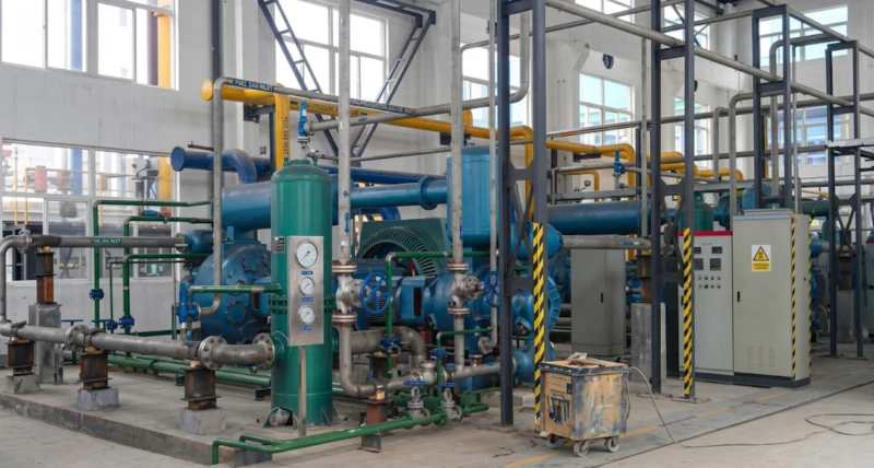
Installed at Customer Sites
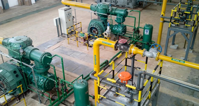
Oxygen and nitrogen compressors from this three-series range are operating in medical gas plants, industrial gas filling stations, steel mills, chemical plants, and PSA nitrogen booster installations. The following images show representative customer site installations.
How to Specify an Oxygen or Nitrogen Compressor
Verify Gas Identity and Purity
Verify whether the gas is oxygen, nitrogen, or an oxygen-nitrogen mixture. For oxygen, state the oxygen concentration (95% PSA medical grade, 99.5% ASU industrial grade, or higher) — this determines the oxygen hazard level and the required cleaning standard. For nitrogen from PSA generators, state the residual oxygen content — this affects the applicable safety standard for the compressor room (PSA nitrogen with more than 0.5% residual oxygen is sometimes handled with partial oxygen safety precautions). Never order an oxygen compressor for nitrogen service or vice versa — the cleaning, material, and safety standards are different and non-interchangeable.
Choose the Correct Series for Your Inlet Pressure
If your gas source is near atmospheric (ASU output, PSA oxygen concentrator, or atmospheric vaporisation of liquid oxygen or nitrogen), choose Series A (oxygen) or Series B (nitrogen) with micro-positive-pressure inlet. If your gas source is a PSA nitrogen generator outputting at 0.35 to 0.60 MPa, choose Series C nitrogen booster compressor with 0.40 MPa inlet design — this eliminates the efficiency penalty of throttling PSA output to near atmospheric. If your gas source is a pipeline or storage vessel at intermediate pressure, contact our application team to verify the most appropriate inlet pressure configuration.
Plan Oxygen Safety Systems for Oxygen Compressor Installations
Oxygen compressor rooms require oxygen-specific safety provisions that differ from standard gas compressor rooms. Combustible materials must be excluded from the compressor room — no lubricating oil containers, no hydrocarbon-based cleaning agents, no rubber hoses in oxygen service. Oxygen pipework must be degreased and oxygen-cleaned prior to connection. Safety relief valves must discharge to a safe outdoor location, not to the compressor room. Discharge temperature monitoring with automatic shutdown is mandatory — maximum discharge temperature per stage is 160 deg C for oxygen service, more conservative than the 180 deg C limit for air compressors, because of the enhanced oxidation risk at elevated temperature in concentrated oxygen. Fire extinguishers in oxygen compressor rooms must be dry chemical or CO₂ type, not hydrocarbon foam.
Plan Downstream Pressure Vessels and Regulatory Compliance
High-pressure oxygen and nitrogen storage vessels, fill manifolds, and cylinder filling equipment must be designed and certified to the appropriate pressure vessel code for the installation country. Medical oxygen supply chains have additional regulatory requirements — in China under the NMPA medical device framework, and in export markets under ISO 7396, EN 13792, and national equivalents. Our documentation package for each compressor includes design pressure certificate data, pressure test reports, and material certification to support pressure vessel code compliance and regulatory approval for medical oxygen applications. Contact our application team at enquiry stage to determine which documentation package is required for your installation.
Frequently Asked Questions — Oxygen and Nitrogen Compressor
Ready to Specify an Oxygen or Nitrogen Compressor?
Our application engineering team provides free sizing across all three series — Series A oxygen, Series B nitrogen, and Series C PSA nitrogen booster — including oxygen-safety material specification, documentation packages for medical and industrial regulatory approval, PSA generator matching for Series C booster selection, and complete technical documentation. Factory-direct pricing, global export, and custom design within 5.5 kW to 3,000 kW.