
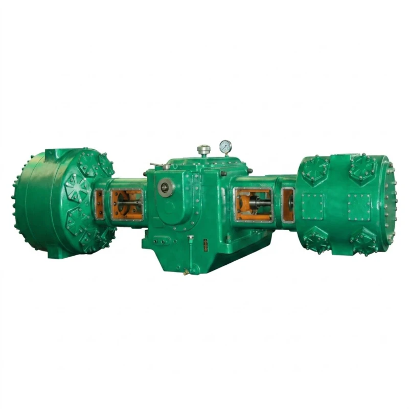
Liquefied Gas and Reaction Gas Compressor — LPG, Refrigerant, Butylene and Process Gas Series
Reciprocating Piston Compressor for Liquefied Petroleum Gas, Refrigerants, Reaction Gas, Butylene, and Tank Truck Unloading · Discharge Pressure 0.40–2.0 MPa · Flow 0.22–385 m³/min · 5.5–2300 kW · 24 Standard Models
The liquefied gas and reaction gas compressor is a purpose-built reciprocating piston compression system engineered for the petrochemical, refinery, refrigeration, and chemical process industries handling liquefied petroleum gas (LPG), liquefied natural gas fractions, refrigerant gases, reaction off-gases, butylene, propylene, propane, and mixed hydrocarbon gas streams. These gases share a common characteristic: they are near their saturation point under typical operating conditions and will partially liquefy if compressor inlet design, inter-stage cooling, and liquid separator provision are not correctly managed. In addition, most of these gas streams are flammable and require explosion-proof or flame-proof motor and electrical equipment, gas-tight sealing, and micro-positive-pressure or controlled inlet pressure design to prevent air ingress.
This series covers 24 standard models with flow from 0.22 m³/min to 385 m³/min at discharge pressures of 0.40 to 2.0 MPa. Mechanical configurations include twin-column single-stage (Twin-col. single-stage), twin-column two-stage (Twin-col. two-stage), four-column single-stage (Four-col. single-stage), and four-column two-stage (Four-col. two-stage) arrangements. The series also covers reaction gas compressors for chemical process service where gases such as propylene, mixed butylene streams, and reactor off-gases must be compressed for recycle or downstream processing. Drive power ranges from 5.5 kW to 2,300 kW with voltage options of 380 V and 6–10 kV. Custom single-unit capacity within 5.5 kW to 3,000 kW available on request for the complete series of liquefied gas medium-pressure compressors.
All models use sealed motor configurations — YB explosion-proof motors for 380 V applications and YAKK/YAKS closed-type high-voltage motors for 6–10 kV applications — together with gas-tight shaft sealing, corrosion-resistant valve and seal materials appropriate for the specific gas composition, inter-stage liquid separation provisions, and controlled inlet pressure design to prevent air ingress into condensable hydrocarbon gas systems. Proven in LPG storage and distribution terminals, petroleum refineries, petrochemical plants, industrial refrigeration facilities, and bulk LPG tank truck unloading stations.
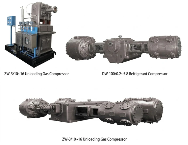
0.40–2.0 MPa
0.22–385 m³/min
24 Standard Models
5.5–2300 kW
380 V / 6 kV / 10 kV
YB / YAKK / YAKS Motors
Reaction Gas Variants
Typical gas types and applications: Liquefied petroleum gas (LPG) storage terminals and distribution stations · LPG tank truck unloading and loading · Propane and butane vapour recovery · Butylene and propylene recovery in petroleum refineries · Mixed C3/C4 hydrocarbon stream compression · Refrigerant gas (ammonia, hydrocarbon refrigerants) compression · Reaction gas recycle and off-gas recovery in petrochemical plants · Catalytic cracking dry gas compression · Dehydrogenation reaction gas recycle · Alkylation unit isobutane makeup
Technical Parameters — Full Model Range (24 Models)
Liquefied Gas Medium-Pressure Compressor · Discharge Pressure 0.40–2.0 MPa · Flow 0.22–385 m³/min
Flow is stated in m³/min at inlet conditions. Inlet condition notation: bracketed pressures e.g. “(inlet 1.00 MPa)” indicate the compressor receives gas at elevated inlet pressure from a storage vessel, pipeline, or upstream process; “micro-positive-pressure” indicates near-atmospheric inlet designed to prevent air ingress. The model name suffix indicates the primary gas service type (e.g. LPG Compressor = liquefied petroleum gas service; Refrigerant Compressor = hydrocarbon refrigerant service; Reaction Gas Compressor = process reaction gas service; Butylene Compressor = butylene stream service; Tank Truck Unloading Compressor = vapour balance unloading service). Custom single-unit capacity within 5.5 kW to 3,000 kW available on request.
| No. | Model / Application | Pattern | Flow (m³/min) | Inlet Condition | Discharge (MPa) | Dimensions L×W×H (mm) | Weight (t) | Motor | Power (kW) | Voltage (V) |
|---|---|---|---|---|---|---|---|---|---|---|
| 1 | ZW-0.22/10~16 LPG Compressor | Twin-col. single-stage | 0.22 | Inlet 1.00 MPa | 1.60 | 1550×985×2013 | 1.00 | YB132M-6 | 5.5 | 380V |
| 2 | ZW-0.32/10~16 LPG Compressor | Twin-col. single-stage | 0.32 | Inlet 1.00 MPa | 1.60 | 1550×985×2013 | 1.00 | YB132M-6 | 11 | 380V |
| 3 | ZW-2/13~18 LPG Compressor | Twin-col. single-stage | 2 | Inlet 1.30 MPa | 1.80 | 2100×1710×2850 | 3.00 | YB250M-6 | 37 | 380V |
| 4 | ZW-4/(1~4)~6.5 Butylene Compressor | Twin-col. single-stage | 3 | Inlet 1.00 MPa | 1.60 | 2650×1550×2580 | 2.50 | YB280S-8 | 37 | 380V |
| 5 | ZW-4.8/8 Butylene Compressor | Twin-col. single-stage | 4.8 | Micro-positive-P | 0.85 | 2250×1296×2200 | 2.50 | YB2280M-6 | 45 | 380V |
| 6 | ZW-5/10~16 LPG Compressor | Twin-col. single-stage | 5 | Inlet 1.00 MPa | 1.60 | 2250×1865×2350 | 3.00 | YB315-10 | 75 | 380V |
| 7 | DW-3/(3~5)~10 LPG Compressor | Twin-col. single-stage | 3 | Inlet 0.30–0.50 MPa | 1.00 | 3570×1350×2400 | 4.00 | YB315S-10 | 45 | 380V |
| 8 | DW-21/8~16 LPG Compressor | Twin-col. single-stage | 21 | Inlet 0.80 MPa | 1.60 | 4640×4200×2060 | 6.00 | YAKK630-16 | 355 | 6–10KV |
| 9 | DW-22.5/4.6~10.5 Refrigerant Compressor | Twin-col. single-stage | 22.5 | Inlet 0.46 MPa | 1.05 | 4600×1730×2050 | 8.00 | YB500-16 | 280 | 380V/6-10KV |
| 10 | DW-25/8~16 LPG Compressor | Twin-col. single-stage | 25 | Inlet 0.80 MPa | 1.60 | 5500×1700×2530 | 12.00 | YAKS630-16 | 400 | 6–10KV |
| 11 | DW-38/0.1~5.6 Butylene Compressor | Twin-col. two-stage | 38 | Inlet 0.01 MPa | 0.56 | 4800×4000×2800 | 20.00 | YB450-12 | 250 | 380V/6-10KV |
| 12 | DW-80/5.8~17 Reaction Gas Compressor | Twin-col. single-stage | 80 | Inlet 0.58 MPa | 1.70 | 7010×3030×2910 | 32.00 | YAKK900-16 | 1600 | 6–10KV |
| 13 | DW-80/1.1~20 Reaction Gas Compressor | Twin-col. single-stage | 80 | Inlet 0.49 MPa | 2.00 | 5900×2110×2530 | 10.00 | YAKK630-14 | 900 | 6–10KV |
| 14 | DW-100/0.2~6.2 Refrigerant Compressor | Twin-col. single-stage | 100 | Inlet 0.02 MPa | 1.90 | 6200×2500×3200 | 15.00 | YAKS710-14 | 630 | 6–10KV |
| 15 | 4MW-86.9/2~19 Reaction Gas Compressor | Four-col. two-stage | 86.9 | Inlet 0.20 MPa | 1.90 | 6400×7600×2600 | 34.00 | TAW1400-18 | 1400 | 6–10KV |
| 16 | 4MW-141/0.3~6.5 Reaction Gas Compressor | Four-col. two-stage | 141 | Inlet 0.03 MPa | 0.65 | 5600×7600×2500 | 26.00 | TAW900-16 | 900 | 6–10KV |
| 17 | 4MW-160/0.12~7.2 Refrigerant Compressor | Four-col. two-stage | 160 | Inlet 0.012 MPa | 0.72 | 6800×3900×2600 | 29.00 | YAKS710-16 | 1000 | 6–10KV |
| 18 | 4MW-160/0.02~6 Refrigerant Compressor | Four-col. single-stage | 160 | Inlet 0.02 MPa | 0.60 | 6800×3900×2600 | 29.00 | YAKS710-16 | 1000 | 6–10KV |
| 19 | 4MW-185/1.7~5.5 Refrigerant Compressor | Four-col. single-stage | 185 | Inlet 0.17 MPa | 0.55 | 6800×3900×2600 | 25.00 | YAKK800-18 | 1250 | 6–10KV |
| 20 | 4MW-193/0.1~7.2 Refrigerant Compressor | Four-col. single-stage | 193 | Inlet 0.01 MPa | 0.72 | 6500×3900×2600 | 32.00 | YAKS800-14 | 1250 | 6–10KV |
| 21 | 4MW-200/0.2~5.8 Refrigerant Compressor | Four-col. two-stage | 200 | Inlet 0.02 MPa | 0.58 | 6510×3905×3400 | 34.00 | YAKK800-16 | 1250 | 6–10KV |
| 22 | 4MW-218/0.2~5.8 LPG Compressor | Four-col. two-stage | 218 | Inlet 0.02 MPa | 0.58 | 6510×3905×3400 | 34.00 | YAKK800-16 | 1120 | 6–10KV |
| 23 | 4MW-270/0.2~5.8 LPG Compressor | Four-col. two-stage | 270 | Inlet 0.02 MPa | 0.58 | 6310×3905×3450 | 35.00 | YAKK900-16 | 1600 | 6–10KV |
| 24 | 4MW-385/0.2~5.5 Refrigerant Compressor | Four-col. single-stage | 385 | Inlet 0.02 MPa | 0.55 | 8000×4200×2600 | 55.00 | TAW2300-18 | 2300 | 6–10KV |
Note: Flow stated in m³/min at inlet conditions. Model name suffixes: LPG Compressor = liquefied petroleum gas service; Refrigerant Compressor = hydrocarbon refrigerant service; Reaction Gas Compressor = petrochemical process reaction gas service; Butylene Compressor = butylene/butene stream service. Inlet condition ranges (e.g. 0.3~0.50 MPa in No. 7) indicate variable inlet pressure operation within the stated range. Custom single-unit capacity within 5.5 kW to 3,000 kW available on request for the complete series of liquefied gas medium-pressure compressors.
Why Liquefied Gas and Reaction Gas Compression Needs Dedicated Equipment
The Phase Behaviour Challenge of Near-Saturation Gas Streams
Liquefied petroleum gas, butylene, propylene, and hydrocarbon refrigerants are all in a near-saturation state during normal compression — meaning that a small decrease in temperature or increase in pressure during compression will cause a portion of the gas to condense to liquid. Liquid entering a reciprocating compression cylinder at high velocity causes hydraulic shock — the incompressible liquid cannot be compressed further and instead transmits the full compression force as an impulse to the piston, connecting rod, and crankshaft, often causing catastrophic mechanical failure in a single stroke. Managing this risk requires: adequate liquid separation upstream of each compression stage with a properly sized knockout drum; controlled cooling temperatures that maintain gas above the dew point at each inter-stage condition; and inlet volume buffers that dampen flow surges and allow any entrained liquid droplets to settle before reaching the cylinder inlet valves. All models in this series incorporate these provisions as standard design features, not as optional additions.
Motor Selection — Why YAKK and YAKS Differ from Standard YB
The three motor families used across this series reflect different electrical and environmental requirements. The YB explosion-proof motor series (380 V, up to 75 kW in this series) uses a flameproof enclosure that contains any internal ignition and prevents flame propagation to the external atmosphere — suitable for Zone 1 and Zone 2 hazardous areas. The YAKK closed-type high-voltage motor series (6–10 kV, typically 900 to 1,600 kW) uses an air-cooled enclosed construction designed for continuous operation in hydrocarbon atmospheres at medium voltage. The YAKS sealed high-voltage motor series provides enhanced sealing for environments with higher concentrations of condensable hydrocarbon vapour — such as LPG terminal compressor rooms where propane and butane vapour concentrations are higher than in a general refinery compressor house. Specifying the correct motor family requires knowing the hazardous area zone classification and the specific hydrocarbon vapour environment of the installation.
Reaction Gas Service — Variable Composition and Fouling Risk
Reaction gas compressors handle process off-gas streams from catalytic reactors — dehydrogenation units, alkylation reactors, fluid catalytic cracking (FCC) units, and polymerisation reactor off-gas recovery. These streams have variable composition as the reactor operates across different conversion conditions and catalyst deactivation stages. Reaction gas streams may also contain trace catalyst fines, polymer deposits, or heavy hydrocarbon condensates that foul valve seats and inter-stage heat exchangers if not managed by appropriate inlet scrubber design. The DW and 4MW series reaction gas models in this series use wider valve clearances, higher valve lift, and valve materials selected for resistance to polymer deposition — features that distinguish them from the LPG and refrigerant models on the same mechanical frame.
5 Core Advantages of This Liquefied Gas Compressor Series
Condensable Gas Phase-Safe Design
Inlet liquid separation, controlled inter-stage temperatures, and inlet buffer volumes are standard design features on all models — not afterthought options. This eliminates the risk of liquid carry-over to the compression cylinder, which is the primary cause of catastrophic mechanical failure in liquefied gas compressors operated on near-saturation hydrocarbon streams. The design principles applied in this series reflect decades of service experience in LPG, refrigerant, and C3/C4 hydrocarbon compression service.
Matched Motor Selection for Every Environment
Three motor families — YB explosion-proof (380 V), YAKK closed high-voltage, and YAKS sealed high-voltage — cover the full range from small LPG cylinder filling stations to large petrochemical plant compression trains. Motor selection is matched to the specific hazardous area zone classification and hydrocarbon vapour environment, ensuring appropriate protection level for each installation rather than a single over-specified or under-specified motor standard applied across all applications.
Wide Flow Range — 0.22 to 385 m³/min
From a compact 5.5 kW ZW-series unit for small LPG station duty through to a 2,300 kW four-column single-stage 4MW-385 for large-scale industrial refrigeration, the 24 standard models cover the complete commercial and industrial scale of liquefied gas compression without requiring custom designs for most applications. The four-column flagship models (4MW-160 to 4MW-385) provide the large-capacity, high-availability option needed for continuous petrochemical plant service where compressor downtime has direct production cost consequences.
Flexible Inlet Pressure — Storage to Near-Atmospheric
The series covers booster configurations receiving LPG from storage tanks at 0.80 to 1.30 MPa through to near-atmospheric inlet models handling vapour from low-pressure refrigerant systems at 0.01 to 0.02 MPa absolute. This range of inlet pressure options allows each compressor to be precisely matched to the actual gas source pressure — eliminating pressure-reducing throttling losses that occur when an atmospheric-inlet model is applied to a pressurised source — while providing the correct compression ratio and stage count for the inlet-to-outlet pressure ratio required.
Proven in Continuous Petrochemical Service
Large-frame DW and 4MW series models operating in Chinese and international refinery and petrochemical service have demonstrated sustained availability of over 98% in continuous hydrocarbon gas service with proper maintenance programmes. The heavy-duty crankshaft, connecting rod, and bearing design used in the large reaction gas models reflects the demanding duty cycle of petrochemical plant compression trains that operate 8,000 hours per year with planned maintenance only at annual or biennial turnaround windows.
Typical Application Scenarios
LPG Terminal and Distribution Station
LPG (propane-butane mixture) is stored in bulk terminals at saturation pressure of 0.5 to 1.6 MPa depending on ambient temperature and LPG composition. LPG compressors at terminals serve two functions: vapour return during liquid loading (returning vapour from the receiving vessel to the supply tanker to maintain pressure balance and prevent liquid sloshing); and vapour recovery from storage tank vapour spaces to maintain inventory and prevent atmospheric venting. ZW and DW series LPG compressor models at 1.0 to 1.6 MPa discharge serve LPG terminal vapour balance and vapour recovery operations, with compact YB or YAKS motor configurations suited to hazardous area terminal compressor houses.
ZW-0.22/10~16 to DW-25/8~16 · 0.22–25 m³/min
Tank Truck LPG Unloading
LPG tank trucks unloading to fixed storage require a vapour return compressor to transfer the vapour from the storage tank back to the truck tank as liquid flows from truck to storage. This vapour balance operation maintains pressure in both vessels to allow continued liquid flow without pump assistance. The DW-3/(3~5)~10 model with variable inlet pressure (0.30 to 0.50 MPa) is specifically designed for tank truck unloading service, where inlet pressure varies as the truck tank empties and storage tank fills. Unloading station compressors must handle this variable inlet pressure without surge or instability.
DW-3/(3~5)~10 · Variable inlet 0.30–0.50 MPa
Butylene and Propylene Refinery Recovery
Petroleum refinery catalytic cracking units produce large quantities of C3 (propylene-propane) and C4 (butylene-butane-isobutylene) hydrocarbon fractions as co-products. These streams are recovered from the FCC main fractionator overhead vapour at near-atmospheric or low positive pressure and must be compressed to saturation pressure for liquid recovery, fractionation, and downstream processing as polymer-grade propylene or butylene. The DW-38/0.1~5.6 butylene compressor (two-stage to 0.56 MPa from 0.01 MPa inlet) and DW-80/5.8~17 reaction gas compressor (single-stage booster from 0.58 MPa to 1.70 MPa) represent the typical compression requirements for C4 stream recovery in a medium-scale refinery.
DW-38/0.1~5.6 · DW-80/5.8~17 · Butylene and reaction gas service
Industrial Refrigeration — Hydrocarbon Refrigerants
Large industrial refrigeration systems for petrochemical plant low-temperature separation, LNG peak shaving, ethylene cold box operation, and propylene refrigeration cycles use propane, ethylene, or propylene as the refrigerant rather than conventional HFC refrigerants. These hydrocarbon refrigerant systems operate at very low evaporator pressures (down to 0.01 MPa absolute for low-temperature propylene service) and compress to condensing pressures of 0.55 to 0.75 MPa. The large four-column refrigerant compressor models — 4MW-160 through 4MW-385 — serve as the primary refrigerant compressor in large propylene and ethylene refrigeration cycles with flows from 160 to 385 m³/min at motor powers from 1,000 to 2,300 kW.
4MW-160/0.02~6 to 4MW-385/0.2~5.5 · Large industrial refrigeration
Dehydrogenation and Alkylation Reaction Gas
Propane dehydrogenation (PDH) to produce propylene and butane dehydrogenation (BDH) to produce butylene generate reactor off-gas streams that contain unconverted feed, product, hydrogen, and light hydrocarbons. These streams must be compressed for separation and recycle. Similarly, alkylation units producing high-octane gasoline blend stocks use isobutane makeup gas that must be compressed from the deisobutaniser overhead vapour at near-atmospheric to alkylation reactor conditions. The 4MW-86.9/2~19 and 4MW-141/0.3~6.5 reaction gas models serve these petrochemical compression duties at 86 to 141 m³/min and 900 to 1,400 kW.
4MW-86.9/2~19 · 4MW-141/0.3~6.5 · Reaction gas recycle
Refrigerant Compressor for Chemical Cold Utility
Chemical plants operating low-temperature reactors, cold separation columns, and product chilling systems require refrigeration utility supplied at multiple temperature levels from a central refrigeration train. The DW-22.5/4.6~10.5 refrigerant compressor (single-stage from 0.46 MPa inlet to 1.05 MPa discharge, 280 kW) and DW-100/0.2~6.2 refrigerant compressor (single-stage from 0.02 MPa to 1.90 MPa, 630 kW) serve as intermediate and high-stage refrigerant compressors in multi-stage refrigeration cycles providing cold utility to chemical plant process consumers at different temperature levels from minus 20 deg C to minus 45 deg C.
DW-22.5/4.6~10.5 · DW-100/0.2~6.2 · Chemical cold utility
Installed at Customer Sites
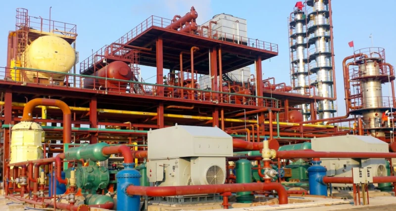
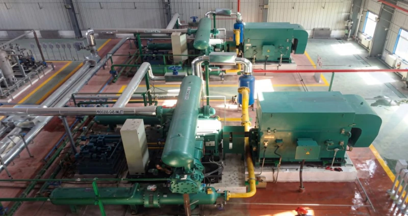
Liquefied gas and reaction gas compressors from this series are operating in LPG terminals, petroleum refineries, petrochemical plants, and industrial refrigeration facilities. The following images show representative customer site installations.
How to Specify a Liquefied Gas or Reaction Gas Compressor
Define Gas Composition and Phase Behaviour
Unlike a permanent gas (air, nitrogen, hydrogen) where composition is fixed and condensation risk is absent, a liquefied gas compressor must be designed around the complete gas phase envelope of the specific stream being compressed. The gas composition analysis must include all components at their expected concentration range across operating seasons and process conditions. From this composition, our application engineers calculate the saturation pressure and temperature at each proposed stage discharge condition, confirming that the inter-stage cooling temperature set points maintain the gas above its dew point throughout the compression train and avoid liquid formation in the inter-stage pipework and liquid separators.
Specify Inlet Pressure — Storage Booster or Near-Atmospheric
LPG storage booster compressors receive gas at storage vessel saturation pressure — typically 0.6 to 1.4 MPa depending on LPG composition and ambient temperature — and boost to a slightly higher pressure for vapour balance or transfer duty. These are single-stage configurations with a relatively low compression ratio per stage. Near-atmospheric inlet models (0.01 to 0.05 MPa inlet) for refrigerant suction or reaction gas from low-pressure separators require two stages to achieve 0.55 to 0.75 MPa discharge pressure within acceptable discharge temperature limits. Clearly stating the inlet pressure and its seasonal or operational range is essential for stage count and cylinder bore selection.
Choose Motor Type for Hazardous Area Classification
Hydrocarbon gas compressor installations are classified as hazardous areas — at minimum Zone 2, and Zone 1 within the immediate vicinity of the compressor cylinder and seal areas. The hazardous area zone classification, gas group (IIA for propane-butane, IIB for propylene, ethylene, and butylene), and temperature class (T1 to T4 depending on gas auto-ignition temperature) together determine the required motor protection standard. Small 380 V models use YB explosion-proof motors rated for the applicable gas group. Large 6–10 kV models use YAKK or YAKS closed-type motors — the selection between YAKK and YAKS depends on the expected concentration of hydrocarbon vapour in the motor cooling air path. Our application team can advise on motor selection based on site hazardous area documentation.
Plan Liquid Separation and Process Safety Systems
Each compressor model requires an inlet knockout drum sized for the gas flow and expected liquid loading, with a high liquid level trip that shuts down the compressor before liquid reaches the cylinder inlet. Additionally, discharge temperature monitoring with automatic shutdown (typically set at 150 deg C for hydrocarbon service), discharge over-pressure protection via safety relief valve to a flare header, seal gas or purge system for shaft seal leakage management, and hydrocarbon gas leak detection at the compressor are mandatory safety provisions. These systems are designed as part of the compressor package and their specification must be included in the compressor enquiry to allow a complete safety system to be provided.
Frequently Asked Questions — Liquefied Gas and Reaction Gas Compressor
Ready to Specify a Liquefied Gas or Reaction Gas Compressor?
Our application engineering team provides free sizing for LPG, refrigerant, and reaction gas compressors — including phase behaviour analysis, stage pressure optimisation, motor type recommendation for your hazardous area classification, liquid separation system sizing, and complete technical documentation for regulatory compliance. Factory-direct pricing, global export, and custom design within 5.5 kW to 3,000 kW.