
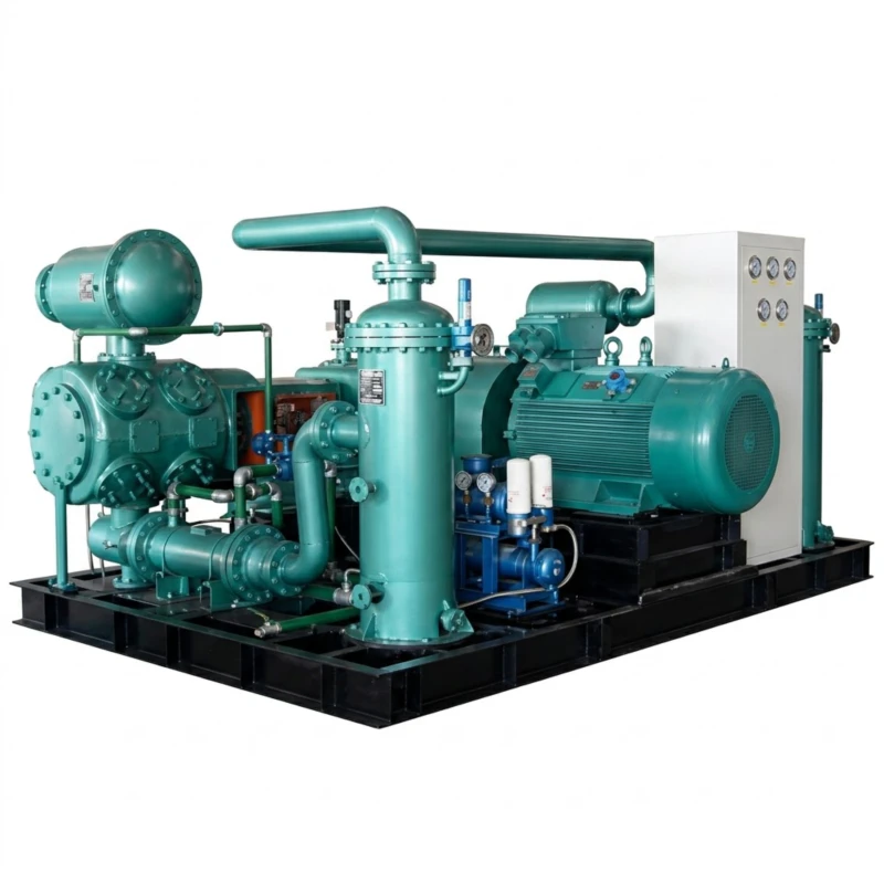
Gas Compressor — Low-Pressure and Medium/High-Pressure Two-Series
Reciprocating Piston Compressor for Coal Gas, Coke Oven Gas, Water Gas, CO, Coal Bed Methane, Biogas, and Mixed Industrial Gases · Low-Pressure 0.10–1.0 MPa, 1–600 m³/min · Medium/High-Pressure 1.2–6.0 MPa, 1–300 m³/min · 11–3000 kW
The gas compressor is a purpose-built reciprocating piston compression system for the safe and reliable handling of combustible, toxic, and corrosive industrial gases including coal gas, coke oven gas, semi-water gas, water gas, carbon monoxide (CO), coal bed methane (CBM), biogas, marsh gas, and mixed gas streams. These gases present hazards — including flammability, toxicity, and the presence of corrosive contaminants such as hydrogen sulfide (H₂S), tar vapours, and ammonia — that make standard air compressors completely unsuitable. Dedicated gas compressors incorporate gas-tight sealing systems, explosion-proof or flame-proof electrical equipment, corrosion-resistant wetted materials, micro-positive-pressure inlet designs, and inter-stage scrubbing provisions to safely handle these process gases across the complete pressure range required by chemical, energy, and metallurgical industries.
Series A — Low-Pressure Gas Compressor covers 42 standard models with flow from 1 m³/min to 600 m³/min at discharge pressures of 0.10 to 1.0 MPa, serving gas pipeline transport, chemical plant feed compression, and gas distribution applications. Series B — Medium/High-Pressure Gas Compressor covers 15 standard models with flow from 1 m³/min to 300 m³/min at discharge pressures of 1.2 to 6.0 MPa, serving chemical synthesis feed (methanol, ammonia, synthetic natural gas), gas storage, and high-pressure process requirements. Drive power spans 11 kW to 3,000 kW with voltage options of 380 V, 6 kV, and 10 kV. Custom single-unit capacity within 11 kW to 3,000 kW available on request for both gas compressors and gas boosters.
All models use micro-positive-pressure inlet design to prevent air ingress into the gas system, explosion-proof or flame-proof motor and electrical equipment, corrosion-resistant valve and seal materials appropriate for the specific gas composition, and gas-tight shaft sealing with leakage collection. Proven in coal chemical plants, coking operations, synthetic gas plants, methanol synthesis, biogas upgrading, and coal bed methane compression stations worldwide.
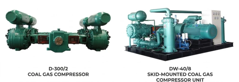
Low-P: 0.10–1.0 MPa
Med/High-P: 1.2–6.0 MPa
1–600 m³/min
57 Standard Models
11–3000 kW
380 V / 6 kV / 10 kV
Micro-Positive Inlet Pressure
Typical gas types handled: Coal gas (town gas) · Coke oven gas · Semi-water gas · Water gas · Carbon monoxide (CO) · Coal bed methane (CBM) · Biogas and marsh gas · Landfill gas · Synthetic gas (syngas) · Mixed hydrogen-containing gas · Converter gas · Blast furnace gas (with appropriate conditioning) · Methane-rich process gas
Series A — Low-Pressure Gas Compressor
Gas Pipeline Transport and Low-Pressure Process Feed · Discharge Pressure 0.10–1.0 MPa · Flow 1–600 m³/min
Series A covers 42 standard models in twin-column single-stage and two-stage configurations (Twin-col. single-stage / Twin-col. two-stage) and four-column two-stage configuration for large-flow applications. All models use micro-positive-pressure inlet design. Flow stated in m³/min at inlet conditions. Custom single-unit capacity within 11 kW to 3,000 kW available on request.
| No. | Model | Pattern | Flow (m³/min) | Pressure (MPa) | Dimensions L×W×H (mm) | Weight (t) | Power (kW) | Voltage (V) |
|---|---|---|---|---|---|---|---|---|
| 1 | 2Z-1/8 | Twin-col. single-stage | 1 | 0.80 | 830×763×1191 | 0.80 | 11 | 380 |
| 2 | 2Z-2/4 | Twin-col. single-stage | 2 | 0.40 | 830×763×1191 | 0.80 | 15 | 380 |
| 3 | ZW-3/8 | Twin-col. single-stage | 3 | 0.80 | 2500×1296×2220 | 2.00 | 30 | 380 |
| 4 | 2Z-4.5/3 | Twin-col. single-stage | 4.5 | 0.30 | 763×720×1274 | 0.40 | 22 | 380 |
| 5 | 3L-6/6 | Twin-col. two-stage | 6 | 0.60 | 2310×910×1954 | 1.80 | 45 | 380 |
| 6 | 3L-9/10 | Twin-col. two-stage | 9 | 1.00 | 2310×910×2020 | 1.80 | 55 | 380 |
| 7 | 3L-10/3.5 | Twin-col. single-stage | 10 | 0.35 | 2187×910×2186 | 1.70 | 45 | 380 |
| 8 | 3L-10/6 | Twin-col. two-stage | 10 | 0.60 | 2310×910×2020 | 1.80 | 55 | 380 |
| 9 | LW-15/8 | Twin-col. two-stage | 15 | 0.80 | 2632×1550×2330 | 3.00 | 110 | 380 |
| 10 | LW-20/3.5 | Twin-col. single-stage | 20 | 0.35 | 2370×910×2070 | 2.00 | 75 | 380 |
| 11 | 4L-20/8(10) | Twin-col. two-stage | 20 | 0.80 (1.00) | 2450×1550×2150 | 2.80 | 132 | 380 |
| 12 | 4L-20/10 | Twin-col. two-stage | 20 | 1.00 | 2450×1550×2150 | 2.60 | 132 | 380 |
| 13 | 3L-25/1.5 | Twin-col. single-stage | 25 | 0.15 | 2500×910×2180 | 2.50 | 75 | 380 |
| 14 | 4L-25/3.5 | Twin-col. two-stage | 25 | 0.35 | 2450×1550×2150 | 2.60 | 132 | 380 |
| 15 | 5.5-25/8 | Twin-col. two-stage | 25 | 0.80 | 2750×1550×2150 | 4.20 | 185 | 380 |
| 16 | LW-30/3.5 | Twin-col. two-stage | 30 | 0.35 | 2990×1600×2370 | 3.40 | 132 | 380 |
| 17 | LW-40/4 | Twin-col. two-stage | 40 | 0.40 | 2890×1600×2739 | 4.50 | 160 | 380 |
| 18 | LW-40/8 | Twin-col. two-stage | 40 | 0.80 | 2890×1600×2773 | 5.00 | 250 | 380/6K or 10K |
| 19 | LW-45/8 | Twin-col. two-stage | 45 | 0.80 | 2890×1600×2773 | 7.00 | 280 | 380/6K or 10K |
| 20 | LW-50/4 | Twin-col. two-stage | 50 | 0.40 | 2630×1600×2235 | 6.00 | 200 | 380 |
| 21 | LW-50/8 | Twin-col. two-stage | 50 | 0.80 | 2630×1600×2235 | 6.50 | 315 | 380/6K or 10K |
| 22 | L5.5-60/4 | Twin-col. two-stage | 60 | 0.40 | 2995×1600×2170 | 5.00 | 250 | 380/6K or 10K |
| 23 | LW-60/4 | Twin-col. two-stage | 60 | 0.40 | 2630×1600×2235 | 6.50 | 250 | 380/6K or 10K |
| 24 | LW-80/2.2 | Twin-col. single-stage | 80 | 0.22 | 2600×1600×2235 | 6.50 | 250 | 380/6K or 10K |
| 25 | L8-90/1.5 | Twin-col. single-stage | 90 | 0.15 | 2750×1500×2820 | 6.00 | 250 | 380/6K or 10K |
| 26 | LB-100/2.2 | Twin-col. single-stage | 100 | 0.22 | 2750×1500×2820 | 6.00 | 315 | 380/6K or 10K |
| 27 | D-46/6 | Twin-col. two-stage | 46 | 0.60 | 5000×1450×2400 | 6.00 | 280 | 380/6K or 10K |
| 28 | D-60/8 | Twin-col. two-stage | 60 | 0.80 | 5000×1450×3300 | 6.50 | 400 | 6K/10K |
| 29 | DW-60/8 | Twin-col. two-stage | 60 | 0.80 | 5000×1450×3300 | 6.50 | 400 | 6K/10K |
| 30 | DW-70/8 | Twin-col. two-stage | 70 | 0.80 | 6000×2050×2525 | 13.00 | 450 | 6K/10K |
| 31 | DW-90/3 | Twin-col. single-stage | 90 | 0.30 | 5400×3540×2700 | 11.00 | 350 | 6K/10K |
| 32 | DW-100/4 | Twin-col. two-stage | 100 | 0.40 | 5456×3518×2535 | 13.00 | 450 | 6K/10K |
| 33 | DW-100/8 | Twin-col. two-stage | 100 | 0.80 | 5456×3518×2535 | 13.50 | 630 | 6K/10K |
| 34 | DW-120/1.5 | Twin-col. single-stage | 120 | 0.15 | 5000×1650×2450 | 6.20 | 355 | 6K/10K |
| 35 | DW-120/4 | Twin-col. two-stage | 120 | 0.40 | 5600×3540×2550 | 13.00 | 550 | 6K/10K |
| 36 | DW-120/8 | Twin-col. two-stage | 120 | 0.80 | 6000×3640×3000 | 18.00 | 630 | 6K/10K |
| 37 | DW-150/2.5 | Twin-col. single-stage | 150 | 0.25 | 6250×2100×2735 | 15.00 | 500 | 6K/10K |
| 38 | DW-150/4 | Twin-col. two-stage | 150 | 0.40 | 6000×3640×3000 | 17.00 | 710 | 6K/10K |
| 39 | DW-200/2.5 | Twin-col. single-stage | 200 | 0.25 | 6250×2100×2735 | 15.00 | 680 | 6K/10K |
| 40 | D-248/1.5 | Twin-col. single-stage | 248 | 0.15 | 7200×3505×2820 | 14.00 | 630 | 6K/10K |
| 41 | DW-300/2.5 | Twin-col. single-stage | 300 | 0.25 | 7200×3505×2820 | 27.00 | 1200 | 6K/10K |
| 42 | HW-400/2.5 | Four-col. two-stage | 400 | 0.25 | 6250×7200×2735 | 30.00 | 1400 | 6K/10K |
| 43 | 4MW-250/4.5 | Four-col. two-stage | 250 | 0.45 | 7200×7300×2820 | 34.00 | 1200 | 6K/10K |
| 44 | 4MW-250/4.5 | Four-col. two-stage | 600 | 0.45 | 7200×7300×2820 | 36.00 | 1400 | 6K/10K |
Note: All Series A models use micro-positive-pressure inlet design. Pressure values in parentheses indicate dual rating available on same frame. Custom single-unit capacity within 11 kW to 3,000 kW available on request.
Series B — Medium/High-Pressure Gas Compressor
Chemical Industry Mid-to-High-Pressure Gas Process Feed · Discharge Pressure 1.2–6.0 MPa · Flow 1–300 m³/min
Series B covers 15 standard models in twin-column three-stage and four-column three-stage configurations for medium and high-pressure gas process applications — methanol synthesis gas feed, synthetic natural gas (SNG) compression, and industrial gas boosting. All models use micro-positive-pressure inlet design. Custom single-unit capacity within 11 kW to 3,000 kW on request. Gas booster compressor designs also available within this custom range.
| No. | Model | Pattern | Flow (m³/min) | Pressure (MPa) | Dimensions L×W×H (mm) | Weight (t) | Power (kW) | Voltage (V) |
|---|---|---|---|---|---|---|---|---|
| 1 | ZW-3.8/13 | Twin-col. 3-stage | 3.8 | 1.30 | 1947×900×2580 | 3.20 | 45 | 380 |
| 2 | ZW-5.3/16 | Twin-col. 3-stage | 5.3 | 1.60 | 2180×910×2200 | 1.80 | 55 | 380 |
| 3 | ZW-15/13 | Twin-col. 3-stage | 15 | 1.30 | 2764×2000×3277 | 5.00 | 132 | 380 |
| 4 | LW-12/10 | Twin-col. 3-stage | 12 | 1.00 | 2764×2000×3277 | 5.00 | 110 | 380 |
| 5 | LW-20/18 | Twin-col. 3-stage | 20 | 1.80 | 2500×1600×2800 | 6.00 | 220 | 380 |
| 6 | LW-22/25 | Twin-col. 3-stage | 22 | 2.50 | 6000×1600×2800 | 6.50 | 240 (250) | 380/6K or 10K |
| 7 | LW-25/16 | Twin-col. 3-stage | 25 | 1.60 | 3920×1800×2465 | 6.80 | 280 | 380/6K or 10K |
| 8 | LW-28/25 | Twin-col. 3-stage | 28 | 2.50 | 3920×1685×2335 | 6.50 | 315 | 380/6K or 10K |
| 9 | DW-40/25 | Twin-col. 3-stage | 40 | 2.50 | 6585×3595×2095 | 13.00 | 450 | 6K/10K |
| 10 | DW-50/25 | Twin-col. 3-stage | 50 | 2.50 | 6585×3595×2095 | 13.00 | 500 | 6K/10K |
| 11 | DW-60/25 | Twin-col. 3-stage | 60 | 2.50 | 8500×2440×3020 | 17.00 | 600 | 6K/10K |
| 12 | DW-70/25 | Twin-col. 3-stage | 70 | 2.50 | 8500×2440×3020 | 17.00 | 710 | 6K/10K |
| 13 | 4MW-85/18 | Four-col. 3-stage | 85 | 1.80 | 6500×5000×3200 | 26.00 | 800 | 6K/10K |
| 14 | 4MW-180/16 | Four-col. 3-stage | 180 | 1.60 | 7800×8000×2700 | 37.00 | 1800 | 6K/10K |
| 15 | 4MW-230/25 | Four-col. 3-stage | 230 | 2.50 | 8000×8000×2700 | 40.00 | 2300 | 6K/10K |
Note: Custom single-unit capacity within 11 kW to 3,000 kW available on request for Series B gas compressors and gas booster compressors. Contact our technical team for specific gas composition, inlet conditions, and process pressure requirements to determine the appropriate model and configuration.
Why Industrial Gas Compression Requires Dedicated Equipment
Gas Composition and Hazard Classification
The gases handled by this compressor series — coal gas, coke oven gas, water gas, carbon monoxide, biogas, and coal bed methane — share several hazardous characteristics that standard air compressors cannot accommodate. These gases are flammable across wide concentration ranges in air (coal gas approximately 5% to 33%, coke oven gas approximately 6% to 30%, CO approximately 12% to 75%), making any air ingress into the gas system a potential explosion and fire hazard. Several also contain toxic components: carbon monoxide is acutely toxic above 50 ppm and CO-rich gases like water gas and semi-water gas may contain 30% to 50% CO by volume. Many industrial gas streams also contain corrosive impurities — hydrogen sulfide (H₂S) from coke oven gas and biogas attacks standard carbon steel valve seats and piston rods, forming iron sulfide deposits that jam valve mechanisms. Condensable components including tar vapours and naphthalene present in coke oven gas can solidify in inter-stage coolers and cause blockage if temperature control is inadequate.
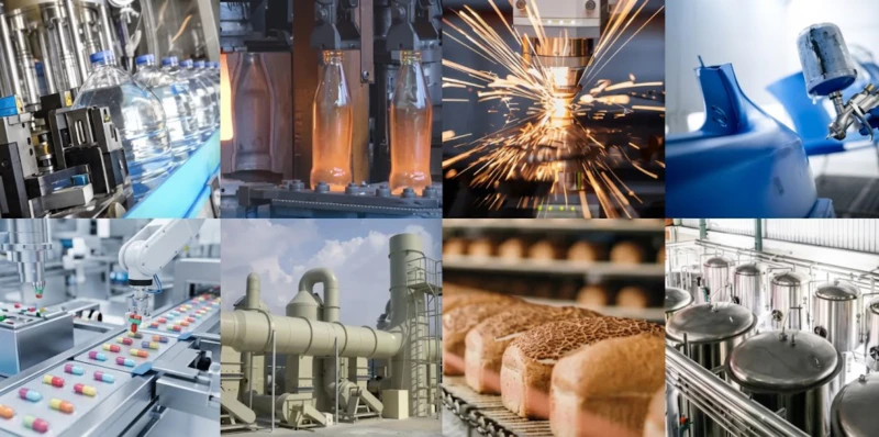
Micro-Positive-Pressure Inlet Design
All models in this series use micro-positive-pressure inlet design, maintaining the compressor inlet at a controlled slight positive pressure (approximately 0.005 to 0.03 MPa above atmospheric). This ensures that any leakage at the inlet side is outward — gas leaking to atmosphere and collected by the ventilation system — rather than inward air ingress that would form explosive gas-air mixtures inside the compression system. This design eliminates the most common cause of gas compressor incidents: air ingress during start-up, shutdown, or when inlet gas supply pressure momentarily drops below atmospheric.
Series A versus Series B — Choosing the Right Pressure Range
Series A (0.10 to 1.0 MPa) covers the gas collection, purification feed, and pipeline transport stage of most coal chemical and gas supply chains — where large volumes of gas at modest pressure ratios must be moved economically. Single-stage models handle the very-low-pressure recovery duty (0.10 to 0.35 MPa), while two-stage models cover the pipeline and process feed pressure range of 0.35 to 1.0 MPa. Series B (1.2 to 6.0 MPa) covers the synthesis feed compression stage — where purified syngas must be raised to the reactor inlet pressure for methanol, ammonia, or SNG synthesis — using three-stage configurations with comprehensive inter-stage cooling and liquid separation to handle the higher compression ratios safely. Many coal chemical plants use both series in cascade: Series A from gas holder to purification, Series B from purification to synthesis.
5 Core Advantages of This Gas Compressor Series
Complete 0.10 to 6.0 MPa Coverage
With 57 standard models spanning gas collection at 0.10 MPa through to synthesis feed at 6.0 MPa in a unified product family, this two-series range eliminates the need for multiple supplier relationships across the gas supply chain. From gas holder outlet compression through pipeline transport, purification feed, and final synthesis reactor feed, a single manufacturer provides technically consistent equipment with unified spare parts catalogues and application support.
Inherent Safety Through Positive-Pressure Design
The micro-positive-pressure inlet standard on all models eliminates the primary cause of gas compressor safety incidents. Combined with gas-tight shaft sealing with leakage collection and monitoring, explosion-proof or flame-proof electrical equipment for Zone 1 or Zone 2 hazardous areas, and discharge temperature monitoring with automatic shutdown, the safety architecture addresses combustible gas hazards at the design level rather than relying on operational procedures alone.
Gas-Composition-Specific Material Specification
Valve plates, seats, piston rod materials, seals, and inter-stage cooler materials are specified according to the actual gas composition for each application. H₂S-containing gases such as coke oven gas and biogas require sour-service-rated materials for all wetted components. CO-rich gases such as water gas require CO-resistant sealing materials. Tar-containing gases require heated inter-stage separators. Ordering a gas compressor requires specifying the gas composition and impurity levels — our application engineers use this data to specify appropriate materials for each installation.
Large Capacity for Industrial-Scale Gas Processing
The four-column Series A flagship models — HW-400/2.5 (400 m³/min at 0.25 MPa, 1,400 kW) and 4MW-250/4.5 (600 m³/min at 0.45 MPa, 1,400 kW) — serve the largest coal chemical plant gas transport requirements with a single unit, while the four-column Series B models — 4MW-180/16 (180 m³/min at 1.60 MPa, 1,800 kW) and 4MW-230/25 (230 m³/min at 2.50 MPa, 2,300 kW) — provide synthesis feed compression for large-scale methanol and SNG plants without requiring multiple parallel compressor units.
Field-Maintainable with Gas-Service Validated Spares
Gas compressor maintenance requires gas-service-validated spare parts — valve assemblies made from H₂S-resistant alloys, piston rings appropriate for the gas molecular weight, and seals compatible with the specific gas composition. Our spare parts programme supplies pre-validated components for each model and gas application, and our application engineers can advise on maintenance intervals specific to the gas composition and operating conditions at each installation.
Typical Application Scenarios
Coal Gas and Coke Oven Gas Recovery
Coking plants produce large quantities of coke oven gas — a mixture of hydrogen, methane, CO, and other hydrocarbons — as a by-product of coal carbonisation. This gas is collected from the coke ovens at near-atmospheric pressure and must be compressed for transport to gas holders, purification columns, and downstream consumers including power generation, district heating, and chemical synthesis. Series A single-stage models (3L-6/6 through DW-100/4) cover the primary compression stage from coke oven battery to gas handling network at 0.40 to 0.80 MPa.
Series A: 3L-6/6 to DW-150/4 · 6–150 m³/min
Coal Bed Methane (CBM) Gathering
Coal bed methane wells produce gas at wellhead pressures that decline over time, typically falling to 0.10 to 0.30 MPa at mature field conditions. Gathering compressors boost the wellhead gas to pipeline pressure (0.40 to 1.0 MPa) for transport to processing facilities or gas grid injection. Series A low-pressure models — particularly the DW-series single-stage variants (DW-90/3, DW-120/1.5, DW-150/2.5) — serve CBM field gathering stations where large gas volumes at low pressure must be transported economically with minimum inter-stage pressure loss.
Series A: DW-90/3 to DW-300/2.5 · 90–300 m³/min
Biogas Upgrading and Injection
Biogas from anaerobic digestion of organic waste, agricultural residues, or wastewater sludge contains approximately 55% to 70% methane and 30% to 45% CO₂, with traces of H₂S and moisture. Compression is required both for biogas upgrading membrane or pressure swing adsorption (PSA) processes, which operate at 0.4 to 1.0 MPa, and for injection of upgraded biomethane into the gas grid at 0.8 to 4.0 MPa. Series A and Series B models cover the complete compression train from raw biogas feed at low pressure through to grid injection pressure, with H₂S-resistant materials standard for biogas service.
Series A: LW-20/3.5 to DW-150/4 | Series B: ZW-5.3/16 to DW-50/25
Methanol Synthesis Gas Feed
Methanol production from coal-derived syngas requires the purified gas feed — a mixture of CO, CO₂, and hydrogen — to be compressed to the methanol synthesis reactor inlet pressure of typically 5.0 to 6.0 MPa. Series B medium-to-high-pressure models (DW-40/25 through 4MW-230/25) provide the synthesis feed compression stage for medium and large-scale coal-to-methanol plants. Large methanol plants with output of 100,000 to 600,000 tonnes per year may use a single 4MW-230/25 (2,300 kW) or multiple parallel DW-series units for the synthesis gas compression stage.
Series B: DW-40/25 to 4MW-230/25 · 40–230 m³/min
Water Gas and Semi-Water Gas Chemical Process
Water gas (CO plus H₂) and semi-water gas produced by coal gasification are used as synthesis gas for ammonia, methanol, and oxo-synthesis. These gases typically contain 30% to 50% CO by volume and require careful handling due to CO toxicity. Series A models handling water gas use CO-service sealing materials and special shaft seals to prevent CO leakage, which is imperceptible by human senses without detection equipment. Series B compression to synthesis pressure follows purification to remove CO₂ and sulfur compounds in a Rectisol or amine scrubbing unit upstream of the synthesis compressor.
Series A: LW-30/3.5 to DW-150/4 | Series B: LW-20/18 to DW-70/25
Coal Gas Town Gas Distribution
Municipal coal gas supply networks — still operated in some cities for residential heating and cooking — require booster compressors at strategic points in the distribution network to maintain supply pressure as demand varies across the day. Series A low-pressure models (2Z-1/8 through LW-60/4) serve as booster and distribution compressors in town gas networks at 0.40 to 0.80 MPa. The small 2Z-series models (11 to 15 kW) serve individual district supply boost stations, while larger LW and DW series models serve primary network booster stations serving entire urban districts.
Series A: 2Z-1/8 to LW-60/4 · 1–60 m³/min
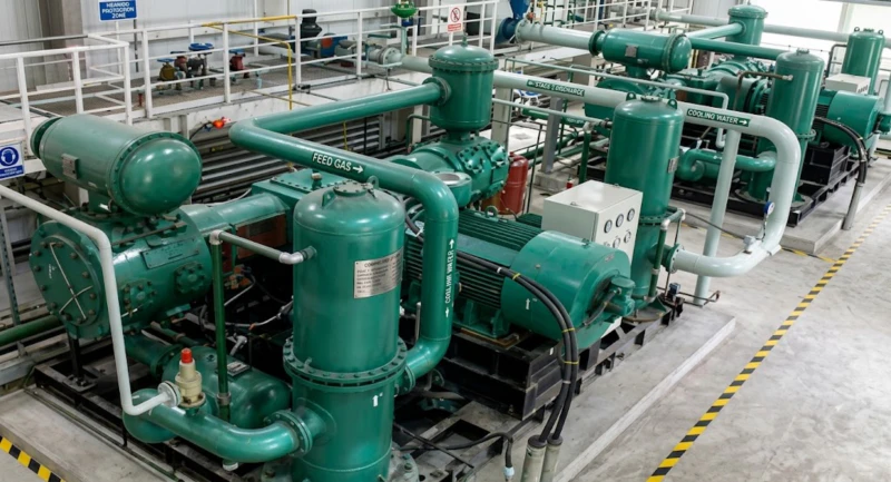
Installed at Customer Sites
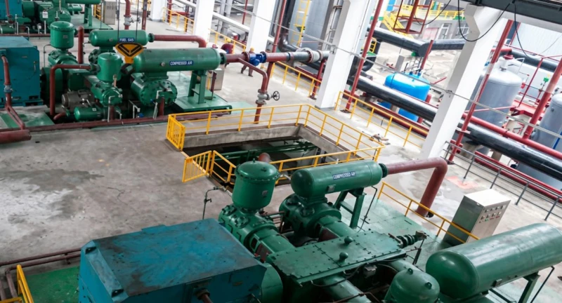
Gas compressors from this series are operating in coal chemical plants, coking facilities, coal bed methane gathering stations, biogas upgrading plants, and municipal gas supply networks. The following images show representative customer site installations.
How to Specify a Gas Compressor — Key Selection Criteria
Provide Full Gas Composition Analysis
Gas compressor specification begins with a complete gas composition analysis — not just the primary combustible components, but all impurities including H₂S concentration, CO content, tar and naphthalene levels, moisture content, and any unusual trace species. This data drives material selection for valves, piston rods, seals, and inter-stage coolers. A gas composition specified as “coal gas” without impurity data is insufficient for equipment specification — coke oven gas from a wet quenching coking plant has very different impurity levels from gas produced by a modern dry quenching plant, and the two require different wetted-part materials. Providing a laboratory gas analysis to our application team is the critical first step in specification.
Define Inlet and Outlet Conditions
Specify inlet pressure (absolute), inlet temperature, outlet (discharge) pressure, and required flow rate at inlet conditions. For gas compressors, the distinction between flow at inlet conditions versus standard conditions (0 deg C, 0.101325 MPa) matters significantly — the actual machine displacement is determined by inlet conditions, not standard conditions. For gases with significant molecular weight differences from air (CO₂ at 44, H₂ at 2, CH₄ at 16), the volumetric flow at inlet may be very different from the equivalent mass flow, and valve sizing and cylinder bore selection depend on inlet gas density and isentropic exponent, not air properties.
Specify Hazardous Area Zone Classification
Gas compressor installations in coal chemical and gas distribution environments are classified as hazardous areas under IEC 60079 or the equivalent national standard. The zone classification of the compressor room and surrounding area determines the required protection level (Ex d, Ex e, Ex n) for all electrical equipment including motors, junction boxes, instruments, and lighting. Our standard motor selection uses the YB explosion-proof series rated for the applicable zone. If the installation requires a specific explosion protection standard or zone rating, this must be specified at ordering stage so the correct Ex-rated motor and instrumentation can be supplied.
Plan for Redundancy and Safe Shutdown
Gas compressor stations in chemical plants and gas networks are typically critical utilities where a compressor failure affects production or gas supply across a large area. Plan for N plus 1 redundancy — at least one standby unit. Safety shutdown systems must include: discharge over-temperature shutdown (standard on all models); discharge over-pressure protection; gas leakage detection in the compressor room connected to emergency shutdown; inlet under-pressure alarm to detect gas supply failure before the system reaches atmospheric pressure; and emergency isolation valves on inlet and outlet that close automatically on shutdown signal. These ancillary safety systems are provided by the plant safety system designer and must be integrated with the compressor control panel.
Frequently Asked Questions — Gas Compressor
Ready to Specify a Gas Compressor for Your Plant?
Our application engineering team provides free gas compressor sizing based on your gas composition analysis, inlet conditions, and process requirements — including material specification for impurity compatibility, hazardous area equipment selection, safety system recommendations, and full technical documentation. Factory-direct pricing, global export, and custom design within 11 kW to 3,000 kW for gas compressors and gas boosters.