
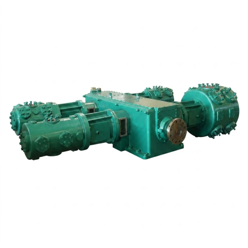
Carbon Dioxide Compressor — Medium/High-Pressure and Low-Pressure Two-Series
Reciprocating Piston CO₂ Compressor for Industrial Gas Processing · Medium/High-Pressure 1.2–10.0 MPa, 2–200 m³/min · Low-Pressure 0.10–1.0 MPa, 2–600 m³/min · 45–3000 kW
The carbon dioxide compressor is a purpose-built reciprocating piston compression system engineered for the specific physical and chemical properties of CO₂ gas in food-grade carbonation, industrial gas recovery, supercritical CO₂ extraction, enhanced oil recovery (EOR), urea synthesis, and carbon capture applications. Unlike general air compressors, CO₂ compressors use sealed gas-tight construction, CO₂-resistant piston ring materials, oil-free or lubricated configurations matched to gas purity requirements, and pressure vessel standards appropriate for handling compressed carbon dioxide safely.
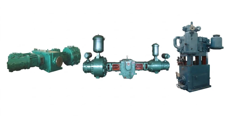
This two-series range covers the complete spectrum of industrial CO₂ compression needs. Series A — Medium/High-Pressure CO₂ Compressor covers 30 standard models from 2 m³/min to 200 m³/min at discharge pressures of 1.2 to 10.0 MPa, in twin-column three-stage, twin-column four-stage, and four-column four-stage configurations. Series B — Low-Pressure CO₂ Compressor covers 26 standard models from 2 m³/min to 600 m³/min at discharge pressures of 0.10 to 1.0 MPa, in twin-column single-stage and two-stage configurations. Drive power spans 45 kW to 3,000 kW with voltage options of 380 V, 6 kV, and 10 kV. Custom single-unit capacity within 11 kW to 3,000 kW available on request across both series.
All models are designed for continuous-duty CO₂ service with gas-tight shaft sealing, CO₂-compatible lubricants or PTFE oil-free rings, inter-stage cooling optimised for CO₂ thermodynamic properties, and material selection to resist carbonic acid corrosion. Proven in food and beverage carbonation plants, brewery CO₂ recovery systems, fertilizer urea synthesis, supercritical CO₂ extraction facilities, and industrial carbon capture installations.
Med/High: 1.2–10.0 MPa
Low: 0.10–1.0 MPa
2–600 m³/min
56 Standard Models
45–3000 kW
380 V / 6 kV / 10 kV
Oil-Free and Lubricated
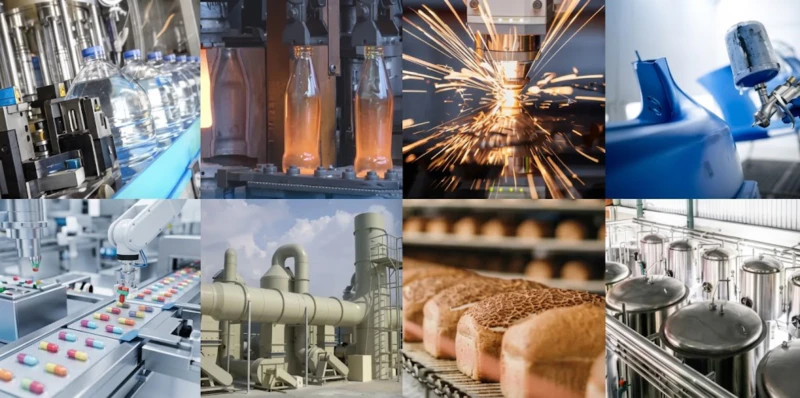
Typical applications: Food and beverage carbonation and CO₂ filling · Brewery CO₂ fermentation gas recovery · Beverage plant CO₂ storage and transfer · Urea and chemical fertilizer synthesis (CO₂ plus ammonia) · Supercritical CO₂ extraction (hop, coffee, herbal, oil) · Enhanced oil recovery (EOR) CO₂ injection · Carbon capture and geological storage (CCS) · Dry ice production · Fire suppression system CO₂ charging · Pharmaceutical CO₂ processing · Low-temperature refrigeration plant CO₂ booster
Series A — Medium/High-Pressure Carbon Dioxide Compressor
For Medium and High-Pressure CO₂ Process Applications · Discharge Pressure 1.2–10.0 MPa · Flow 2–200 m³/min
Series A covers three mechanical configurations: twin-column three-stage (ZW, LW, DW series), twin-column four-stage (DW/40 series with 4.0 MPa rating), and four-column four-stage (4MW series). Model designation: number before slash = flow in m³/min; number after slash = pressure in bar (e.g. DW-30/30 = 30 m³/min at 3.0 MPa). Where two pressure ratings appear (e.g. 4.00/3.00), the compressor frame supports both pressure options. Custom design up to 3,000 kW available.
| No. | Model | Pattern | Flow (m³/min) | Pressure (MPa) | Dimensions L×W×H (mm) | Weight (t) | Power (kW) | Voltage (V) |
|---|---|---|---|---|---|---|---|---|
| 1 | ZW-2/60 Modular | Twin-col. 3-stage | 2 | 6.00 | 1550×1710×1520 | 2.90 | 45 | 380 |
| 2 | ZW-4/25 Modular | Twin-col. 3-stage | 4 | 2.50 | 1920×1900×2580 | 3.97 | 55 | 380 |
| 3 | ZW-5.5/24 | Three-col. 3-stage | 5.5 | 2.40 | 1889×1900×2720 | 3.50 | 75 | 380 |
| 4 | LW-6/18 | Twin-col. two-stage | 6 | 1.80 | 2050×910×2070 | 1.80 | 65 | 380 |
| 5 | LW-8/18 | Twin-col. two-stage | 8 | 1.80 | 2014×910×2006 | 1.80 | 75 | 380 |
| 6 | LW-10/18 | Twin-col. two-stage | 10 | 1.80 | 2632×1550×2332 | 3.00 | 110 | 380 |
| 7 | LW-16/30 | Twin-col. 3-stage | 16 | 3.00 | 3500×2600×1850 | 6.00 | 220 | 380 |
| 8 | LW-20/30 | Twin-col. 3-stage | 20 | 3.00 | 3500×2600×1850 | 6.00 | 240 (250) | 380/6K/10K |
| 9 | LW-20/36 Modular | Twin-col. 3-stage | 20 | 3.60 | 4000×3100×2800 | 9.50 | 250 | 380/6K/10K |
| 10 | LW-25/30 | Twin-col. 3-stage | 25 | 3.00 | 2960×1685×2335 | 6.50 | 280 | 380/6K/10K |
| 11 | DW-25/30 | Twin-col. 3-stage | 25 | 3.00 | 5600×1800×1980 | 6.00 | 280 | 380/6K/10K |
| 12 | DW-25/40(30) | Twin-col. 4-stage | 25 | 4.00 (3.00) | 5930×1450×1800 | 6.00 | 315 (280) | 380/6K/10K |
| 13 | DW-30/30 | Twin-col. 3-stage | 30 | 3.00 | 5600×1800×1980 | 6.00 | 355 | 380/6K/10K |
| 14 | DW-30/40(30) | Twin-col. 4-stage | 30 | 4.00 (3.00) | 6645×3225×2330 | 11.00 | 400 (355) | 6K/10K |
| 15 | DW-32/30 | Twin-col. 3-stage | 32 | 3.00 | 5600×1800×1980 | 6.00 | 400 | 6K/10K |
| 16 | DW-35/30 | Twin-col. 3-stage | 35 | 3.00 | 6645×3225×2330 | 11.00 | 400 | 6K/10K |
| 17 | DW-35/40(30) | Twin-col. 4-stage | 35 | 4.00 (3.00) | 6585×3590×2095 | 13.00 | 450 (400) | 6K/10K |
| 18 | DW-40/40(30) | Twin-col. 4-stage | 40 | 4.00 (3.00) | 6585×3600×2100 | 13.00 | 500 | 6K/10K |
| 19 | DW-44/25 | Twin-col. 3-stage | 44 | 2.50 | 6100×1700×3300 | 11.00 | 450 | 6K/10K |
| 20 | DW-46/30 | Twin-col. 3-stage | 46 | 3.00 | 6100×1700×3300 | 11.50 | 550 | 6K/10K |
| 21 | DW-46/40(30) | Twin-col. 4-stage | 46 | 4.00 (3.00) | 6585×3600×2100 | 13.00 | 600 (550) | 6K/10K |
| 22 | DW-50/25 | Twin-col. 3-stage | 50 | 2.50 | 6100×1700×3300 | 11.00 | 500 | 6K/10K |
| 23 | DW-50/40(30) | Twin-col. 4-stage | 50 | 4.00 (3.00) | 6585×3600×2100 | 13.00 | 600 (550) | 6K/10K |
| 24 | DW-60/40(30) | Twin-col. 4-stage | 60 | 4.00 (3.00) | 8500×4400×3020 | 17.00 | 710 (650) | 6K/10K |
| 25 | DW-70/40(30) | Twin-col. 4-stage | 70 | 4.00 (3.00) | 8500×2440×3020 | 18.00 | 850 | 6K/10K |
| 26 | 4MW-85/40(30) | Four-col. 4-stage | 85 | 4.00 (3.00) | 6400×3300×2800 | 26.00 | 1000 | 6K/10K |
| 27 | 4MW-90/40(30) | Four-col. 4-stage | 90 | 4.00 (3.00) | 6400×3300×2800 | 26.00 | 1050 | 6K/10K |
| 28 | 4MW-100/40(30) | Four-col. 4-stage | 100 | 4.00 (3.00) | 6400×3300×2800 | 26.50 | 1100 | 6K/10K |
| 29 | 4MW-120/40(30) | Four-col. 4-stage | 120 | 4.00 (3.00) | 6800×3900×3200 | 28.50 | 1250 | 6K/10K |
| 30 | 4MW-150/40(30) | Four-col. 4-stage | 150 | 4.00 (3.00) | 8500×3900×3200 | 30.00 | 1700 | 6K/10K |
Note: Custom CO₂ compressor and CO₂ booster compressor designs within 11 kW to 3,000 kW available on request. “(30)” indicates 3.0 MPa optional pressure rating on the same frame. Power values in parentheses apply to the lower pressure option.
Series B — Low-Pressure Carbon Dioxide Compressor
For Low-Pressure CO₂ Process Applications · Discharge Pressure 0.10–1.0 MPa · Flow 2–600 m³/min
Series B covers twin-column single-stage and two-stage configurations for CO₂ recovery, transfer, and low-pressure process supply. Typical uses include brewery and fermentation CO₂ collection at near-atmospheric pressure, CO₂ purification column feed, refrigeration booster service, and low-pressure CO₂ injection. All 26 models use CO₂-grade sealing materials and gas-tight construction. Custom capacity up to 3,000 kW available on request.
| No. | Model | Pattern | Flow (m³/min) | Pressure (MPa) | Dimensions L×W×H (mm) | Weight (t) | Power (kW) | Voltage (V) |
|---|---|---|---|---|---|---|---|---|
| 1 | ZW-6/8 | Twin-col. two-stage | 6 | 0.80 | 2250×1296×2350 | 2.00 | 45 | 380 |
| 2 | LW-10/8 | Twin-col. two-stage | 10 | 0.80 | 2340×910×2070 | 1.80 | 110 | 380 |
| 3 | LW-20/2 | Twin-col. single-stage | 20 | 0.20 | 2632×1550×2332 | 1.80 | 75 | 380 |
| 4 | LW-20/8 | Twin-col. two-stage | 20 | 0.80 | 2630×1550×2332 | 3.00 | 132 | 380 |
| 5 | LW-30/4 | Twin-col. two-stage | 30 | 0.40 | 2975×1550×2370 | 3.40 | 132 | 380 |
| 6 | LW-40/2.5 | Twin-col. single-stage | 40 | 0.25 | 2980×1550×2650 | 3.40 | 160 | 380 |
| 7 | LW-40/4 | Twin-col. two-stage | 40 | 0.40 | 2965×1550×2370 | 3.40 | 160 | 380 |
| 8 | LW-50/5 | Twin-col. two-stage | 50 | 0.50 | 2360×1685×2235 | 6.50 | 240 (250) | 380/6K/10K |
| 9 | LW-60/2.5 | Twin-col. single-stage | 60 | 0.25 | 2995×1600×2170 | 4.82 | 200 | 380/6K/10K |
| 10 | LW-60/4 | Twin-col. two-stage | 60 | 0.40 | 2995×1600×2170 | 4.82 | 240 (250) | 380/6K/10K |
| 11 | DW-60/6 | Twin-col. two-stage | 60 | 0.60 | 5000×1450×1800 | 6.00 | 350 | 380/6K/10K |
| 12 | DW-68/4 | Twin-col. two-stage | 68 | 0.40 | 5100×1450×3200 | 6.80 | 315 | 380/6K/10K |
| 13 | DW-100/6 | Twin-col. two-stage | 100 | 0.60 | 5600×1700×2660 | 13.00 | 550 | 6K/10K |
| 14 | DW-116/6 | Twin-col. two-stage | 116 | 0.60 | 5600×3540×2550 | 13.00 | 630 | 6K/10K |
| 15 | D-120/4 | Twin-col. single-stage | 120 | 0.40 | 5370×1700×2535 | 13.50 | 630 | 6K/10K |
| 16 | DW-120/4 | Twin-col. two-stage | 120 | 0.40 | 5560×3540×2260 | 13.00 | 550 | 6K/10K |
| 17 | DW-130/4 | Twin-col. two-stage | 130 | 0.40 | 5600×3540×2660 | 13.50 | 630 | 6K/10K |
| 18 | DW-150/4 | Twin-col. two-stage | 150 | 0.40 | 6000×3640×3000 | 18.00 | 710 | 6K/10K |
| 19 | DW-190/2.5 | Twin-col. single-stage | 190 | 0.25 | 6250×2100×2735 | 15.00 | 650 | 6K/10K |
| 20 | DW-290/2 | Twin-col. single-stage | 290 | 0.20 | 6500×3800×2535 | 17.00 | 1000 | 6K/10K |
| 21 | DW-300/1 | Twin-col. single-stage | 300 | 0.10 | 6200×3640×2860 | 14.00 | 550 | 6K/10K |
| 22 | DW-325/2 | Twin-col. single-stage | 325 | 0.20 | 6500×3800×2535 | 18.00 | 1100 | 6K/10K |
| 23 | 4MW-180/6.5 | Four-col. two-stage | 180 | 0.65 | 6250×3905×3020 | 26.00 | 1000 | 6K/10K |
| 24 | 4MW-240/6.5 | Four-col. two-stage | 240 | 0.65 | 6250×3905×3020 | 26.00 | 1300 | 6K/10K |
| 25 | HW-380/2.5 | Four-col. single-stage | 380 | 0.25 | 6250×7900×2735 | 28.00 | 1300 | 6K/10K |
| 26 | HW-600/1 | Four-col. single-stage | 600 | 0.10 | 6200×8500×2860 | 30.00 | 1100 | 6K/10K |
Note: Custom CO₂ compressor designs within 11 kW to 3,000 kW available on request for Series B. All Series B models are available in both lubricated and oil-free PTFE piston ring configurations depending on CO₂ purity requirements.
Why CO₂ Compression Requires Dedicated Equipment
CO₂ Physical Properties That Drive Equipment Design
Carbon dioxide has a critical point of 31.1 deg C and 7.38 MPa. When compressed and cooled in the supercritical or near-critical range, CO₂ undergoes large changes in density and can partially liquefy in inter-stage coolers if temperature control is inadequate. Standard air compressor inter-stage coolers are not designed for CO₂ condensation, and liquid CO₂ entering a compression cylinder causes catastrophic mechanical damage. CO₂ compressors use inter-stage separators with liquid level monitoring, higher cooling water temperatures on the LP inter-stage to prevent condensation, and CO₂-specific valve sizing that accounts for the higher molecular weight and different isentropic exponent of CO₂ versus air.
CO₂ in the presence of moisture forms carbonic acid (H₂CO₃), which is corrosive to carbon steel piston rods, cylinder bores, and valve seats. CO₂ compressor wetted parts use corrosion-resistant materials — stainless steel piston rods, special alloy valve plates, PTFE or FKM seals, and corrosion-resistant cylinder bore coatings — to withstand continuous service in wet CO₂ service without accelerated wear. Gas-tight shaft sealing with leakage collection is standard on CO₂ compressors to prevent greenhouse gas emissions and maintain process purity, unlike open-vented air compressor crankcase designs.
Series A — Multi-Stage Compression to Medium and High Pressure
Reaching 3.0 to 4.0 MPa for CO₂ liquid storage charging, urea synthesis column feed, or supercritical extraction requires three or four compression stages with inter-stage cooling and liquid separation between each stage. The twin-column three-stage configuration handles the 1.2 to 3.0 MPa range efficiently for medium-scale applications. The twin-column four-stage and four-column four-stage configurations extend the range to 4.0 MPa for large-scale industrial CO₂ compression — including beverage-grade CO₂ high-pressure storage, chemical synthesis feed, and EOR injection — where sustained high-pressure delivery with low specific energy consumption is critical.
Series B — Recovery and Transfer at Low Pressure
Brewery CO₂ fermentation gas is produced at near-atmospheric pressure (0.01 to 0.05 MPa above atmospheric). Recovering this CO₂ for purification and re-use in carbonation requires a first-stage compressor to raise the gas from near-atmospheric to a pressure suitable for storage, purification, or further compression — typically 0.4 to 0.8 MPa for CO₂ purification column feed or 0.1 to 0.25 MPa for gas transfer and buffer storage. Series B low-pressure CO₂ compressors cover this first-stage recovery function with single-stage and two-stage configurations matched to the actual pressure requirements, achieving high volumetric efficiency at the low pressure ratios of CO₂ recovery service.
5 Core Advantages of This Carbon Dioxide Compressor Series
Purpose-Built for CO₂ Gas Properties
Every design detail is matched to the physical and chemical behaviour of CO₂ under compression — inter-stage separation to handle near-critical phase changes, corrosion-resistant wetted materials for wet CO₂ service, gas-tight shaft sealing to prevent leakage, and valve sizing calibrated for CO₂ molecular weight and isentropic exponent. These are not air compressors adapted for CO₂ use — they are CO₂-native designs that reliably handle gas that would rapidly damage a standard air compressor.
Complete Pressure Coverage — 0.10 to 10.0 MPa
From brewery gas recovery at 0.10 MPa through refrigeration booster at 0.4 to 1.0 MPa to liquid CO₂ storage charging at 2.5 to 4.0 MPa and supercritical extraction at 8.0 to 10.0 MPa, this two-series range covers every industrial CO₂ compression requirement in a unified product family with common spare parts philosophy and consistent technical support.
Food-Grade and Oil-Free Options
For food-grade CO₂ applications — carbonated beverage production, dry ice manufacture, and food packaging atmosphere flushing — Series B and Series A models are available in oil-free PTFE piston ring configuration with food-grade gas path materials, delivering CO₂ free of hydrocarbon contamination to meet beverage industry and food safety standards. The oil-free option uses the same distance piece isolation and PTFE ring technology as our fermentation and PET bottle blowing compressors.
Large Single-Unit Capacity for Industrial Scale
With four-column four-stage Series A models reaching 150 m³/min at 4.0 MPa (1,700 kW) and four-column Series B models handling 600 m³/min at 0.10 MPa (1,100 kW), this series covers the largest industrial CO₂ compression applications including large-scale urea plant CO₂ feed, EOR CO₂ injection stations, and major carbon capture facilities, with single units of the scale required to match industrial plant throughputs.
Field-Serviceable in Process Plant Environment
Piston rings, valve assemblies, shaft seals, and inter-stage gaskets are all field-replaceable during planned maintenance shutdowns by plant maintenance teams. The open crankcase design allows visual inspection of internal components without major disassembly. For process plants operating continuous CO₂ service, the ability to perform maintenance within planned turnaround windows without specialist contractors significantly reduces total cost of ownership versus diaphragm or centrifugal CO₂ compressor alternatives.
Typical Application Scenarios
Food and Beverage CO₂ Carbonation
Carbonated soft drinks, beer, sparkling water, and cider all require food-grade CO₂ dissolved into the beverage under pressure. CO₂ is stored as a liquid in high-pressure tanks at 1.5 to 2.0 MPa and dispensed as gas to the carbonation mixer. The medium-pressure Series A models (LW-6/18 to DW-46/30, 1.8 to 3.0 MPa) serve the CO₂ liquefaction and transfer compression step in beverage CO₂ supply systems. Oil-free piston ring configuration is mandatory for food-grade CO₂ compression.
Series A: LW-6/18 to DW-46/30 (oil-free)
Brewery CO₂ Recovery
Beer fermentation produces large quantities of CO₂ gas at near-atmospheric pressure that can be captured, purified, and recycled for use in cellar gas (tank blanketing), packaging line flushing, and carbonation topping. A medium-scale brewery producing 500,000 hl per year generates approximately 15 to 25 m³/min of recoverable CO₂ from fermenting vessels. Series B low-pressure models (LW-20/2 to LW-60/4, 0.20 to 0.40 MPa) collect fermentation CO₂ and feed it to the purification skid, while a Series A unit provides the high-pressure compression stage for liquid CO₂ storage charging.
Series B: LW-20/2 to LW-60/4 | Series A: ZW-4/25 to LW-25/30
Supercritical CO₂ Extraction
Supercritical CO₂ extraction is used to produce hop extract for brewing, coffee decaffeination, herbal and botanical extracts, and edible oil refining. The process requires CO₂ compressed to supercritical conditions above 7.38 MPa — in practice, extraction vessels typically operate at 15 to 30 MPa. The Series A high-pressure models are the compression stage in a supercritical extraction plant, feeding CO₂ from liquid storage into the extraction autoclave via additional boosting stages. Custom designs within the 11 kW to 3,000 kW range can be engineered for specific supercritical extraction pressures and flow rates.
Series A: ZW-2/60 and above (custom HP stages available)
Urea Synthesis CO₂ Feed
Urea production from ammonia and CO₂ at 14 to 18 MPa requires large quantities of compressed CO₂ at the synthesis column inlet pressure. The CO₂ arrives from ammonia plant recovery at near-atmospheric pressure and must be compressed in multiple stages to synthesis pressure. Series A four-stage models from DW-40/40 through 4MW-150/40(30) cover the first compression stages of urea plant CO₂ trains, with custom high-pressure booster stages engineered for final compression to synthesis column feed pressure. Large urea plants processing 1,000 to 2,000 tonnes per day use multiple parallel Series A units.
Series A: DW-40/40 to 4MW-150/40 + custom HP boosters
Carbon Capture and EOR
Enhanced oil recovery (EOR) injects CO₂ into oil reservoirs at 10 to 25 MPa to mobilise residual oil and improve extraction rates. Carbon capture and storage (CCS) facilities compress captured CO₂ for geological injection at similar pressures. Both applications require large-capacity CO₂ compression at high pressure with high reliability — a compressor failure on an EOR or CCS injection station means significant lost production or storage capacity. The large 4MW series four-column models provide the high-capacity, high-reliability base stage compression for EOR and CCS applications, with custom boosting stages for final injection pressure.
Series A: 4MW-85 to 4MW-150 + custom HP boosters
Dry Ice Production and Industrial CO₂
Dry ice production requires liquid CO₂ at approximately 5.5 MPa saturated at minus 20 deg C, which is allowed to expand through a throttle into dry ice snow. Large CO₂ supply plants serving industrial dry ice manufacturers, fire suppression system installers, and laboratory supply companies compress recovered CO₂ to 2.5 to 4.0 MPa for liquid storage and tanker filling. The LW-16/30 through DW-70/40 series covers the typical capacity range of industrial CO₂ liquefaction compressors for dry ice supply and cylinder filling operations.
Series A: LW-16/30 to DW-70/40(30)
Installed at Customer Sites
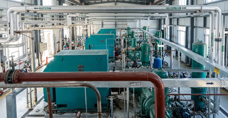
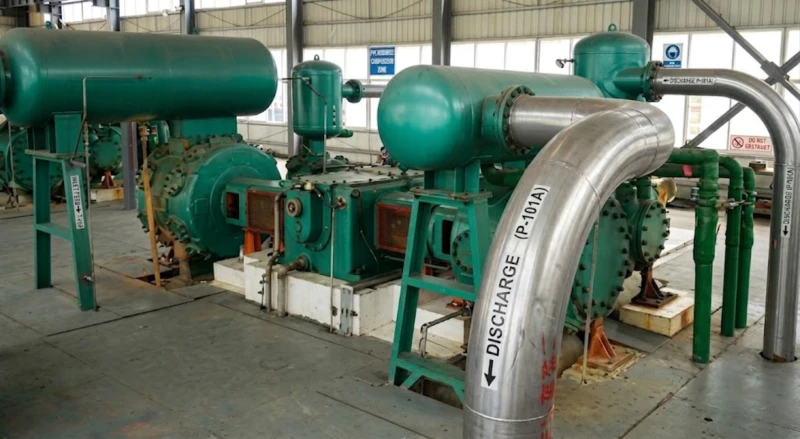
CO₂ compressors from this series are operating in beverage carbonation plants, brewery recovery systems, chemical fertilizer facilities, and industrial gas stations. The following images show representative field installations and scheduled maintenance operations.
How to Specify a CO₂ Compressor — Key Selection Criteria
Determine Inlet and Discharge Pressure
CO₂ compressor inlet pressure varies significantly by application — brewery recovery typically operates at 0.02 to 0.05 MPa above atmospheric, while CO₂ from ethanol plants may arrive at 0.1 to 0.3 MPa. The discharge pressure is determined by the downstream process: liquid CO₂ storage at 2.0 to 2.5 MPa, urea synthesis feed at 14 to 18 MPa (via additional boosting stages), supercritical extraction at 15 to 30 MPa (via additional stages), or low-pressure transfer at 0.4 to 0.8 MPa. Define both inlet and discharge pressures precisely before choosing which series and model to specify.
Specify CO₂ Gas Purity Requirements
Food-grade CO₂ for carbonation must meet strict purity standards (typically 99.9% minimum CO₂, maximum 0.1 ppm oil). This requires oil-free PTFE piston ring configuration with food-grade seals and stainless-steel gas path components. Industrial CO₂ for EOR, urea synthesis, or refrigeration booster service may tolerate a small residual oil content from a lubricated compressor, provided the process is not sensitive to hydrocarbon contamination. Specify the purity class required and whether food-grade or industrial-grade compressor configuration is needed.
Account for CO₂ Near-Critical Behaviour
When compressing CO₂ above approximately 2.0 MPa, inter-stage temperatures must be managed carefully to prevent condensation in the inter-stage cooler. Our CO₂ compressor designs include inter-stage liquid separators with level monitoring and automatic drainage, and the inter-stage cooling temperature set points are specified to maintain CO₂ above its condensation point at each inter-stage pressure. These process details must be discussed with our application engineering team during the specification stage, along with cooling water temperature and CO₂ inlet moisture content.
Plan Shaft Sealing and Emission Control
CO₂ is a greenhouse gas with a Global Warming Potential of 1.0 — shaft seal leakage must be minimised and captured. All CO₂ compressors in this series use gas-tight shaft sealing with leakage collection rather than open atmospheric venting. The collected leakage can be routed back to the compressor inlet or to a low-pressure recovery system. For plants subject to greenhouse gas emissions reporting, shaft seal leakage collection with routing to a flare or recovery system is required. Our application engineers can specify the appropriate sealing and leakage management system for each installation.
Frequently Asked Questions — Carbon Dioxide Compressor
Ready to Specify a CO₂ Compressor for Your Process?
Our application engineering team provides free CO₂ compressor sizing, inter-stage condensation analysis, shaft sealing specification, foundation load data, and complete technical documentation for both Series A and Series B CO₂ compression projects. Factory-direct pricing, global export, and custom design within 11 kW to 3,000 kW.