
An authoritative engineering analysis of adiabatic heat dissipation, structural fin design, forced convection aerodynamics, and electronic thermal cutoffs in 24/7 medical gas generation loops.
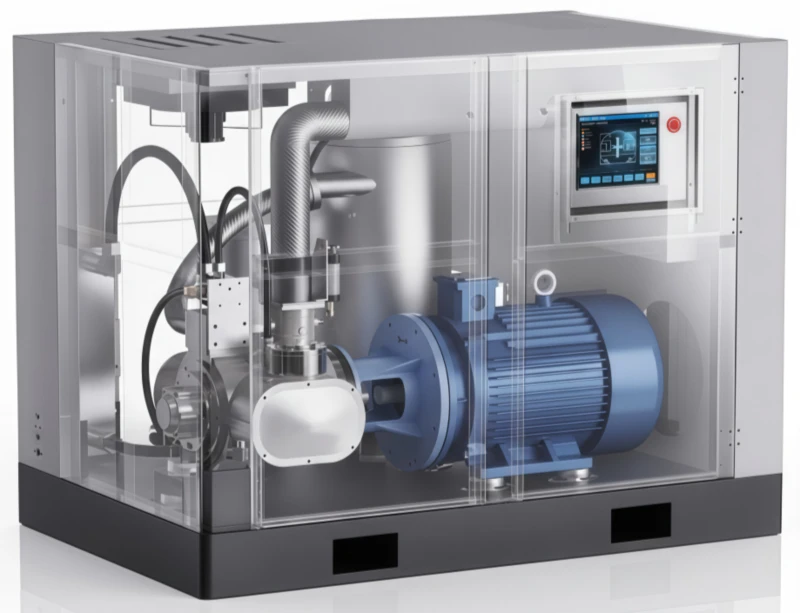
1. Introduction: The Thermal Imperative in Oil-Free Compression Loops
In the field of medical respiratory device engineering and autonomous gas generation, system reliability is directly tied to thermal stability. Pressure Swing Adsorption (PSA) oxygen concentrators depend heavily on a continuous, steady supply of pressurized air to induce molecular separation within synthetic zeolite beds. Because these systems are deployed across life-critical medical wards, home-care settings, and continuous industrial ecosystems, the mechanical prime mover—the miniature air compressor—must operate continuously for thousands of hours without stopping. This intensive 24/7 duty cycle exposes the internal pump assemblies to rigorous thermal challenges that require highly sophisticated engineering solutions.
The primary challenge in managing temperatures inside miniature oxygen concentrator pumps stems from the absolute ban on liquid hydrocarbon lubricants. Traditional air compressors rely on a continuous film of oil to coat sliding surfaces, which absorbs friction heat and seals clearances. In medical and high-purity gas generation applications, however, an oil-free air compressor is a strict requirement to prevent zeolite sieve poisoning and eliminate flammability risks. Operating without an oil film means the system must handle raw friction heat and rapid compression temperature spikes entirely through advanced material selection and structural thermodynamics.
Unmanaged heat buildup causes immediate, compounding mechanical problems. High temperatures cause synthetic piston seals to soften, increase internal air slippage, and alter structural tolerances, leading to a noticeable drop in volumetric efficiency. If a compressor head overheats, the air stream entering the PSA module can exceed optimal limits, disrupting the electrostatic binding of nitrogen and causing oxygen output levels to drop quickly. This detailed guide analyzes the thermodynamics of compression heat, reviews the design of aluminum fin assemblies and forced convection cooling fans, and details smart electronic overload protections to ensure long-term stability in continuous-duty applications.
2. Thermodynamics of Compression Heat: The Adiabatic Challenge
To design an effective thermal management system, engineers must first analyze the physical laws that generate heat inside a micro-compressor. When a gas is compressed within a closed mechanical volume, the work performed by the advancing piston increases the internal kinetic energy of the gas molecules. This process follows the laws of adiabatic compression, where the rapid reduction in volume concentrates gas molecules and leads to an immediate rise in temperature.
This temperature spike is governed by the ideal gas law and the relationship between pressure, volume, and temperature. As the pressure ratio increases from ambient levels to standard PSA targets (typically 3.5 to 6.0 bar), the theoretical temperature of the compressed gas stream can easily exceed 150°C at the exhaust port. In an oil-lubricated system, this heat is absorbed by circulating fluid and carried away to an external radiator. In an oil-free machine, this thermal energy concentrates directly inside the metallic boundaries of the cylinder head, valve plate, and upper cylinder walls.
Furthermore, this compression heat is compounded by sliding friction. As the self-lubricating PTFE cup seal flexes and slides vertically against the cylinder walls, the mechanical resistance generates localized friction heat. This combination of compression heat and sliding friction can cause internal temperatures to rise past safe limits if not managed by effective heat dissipation features. If the compressor head temperature exceeds the material limits of the seals, the system can experience a rapid drop in performance or sudden mechanical failure.
3. Structural Optimization: Advanced Radiator and Heat Sink Fin Topologies
The primary path for removing heat from the internal compression chamber is through conduction into the surrounding metallic housing, followed by dissipation into the ambient air. To maximize this heat transfer, the compressor head and cylinder housing are cast with intricate heat sink fin topologies. These fins increase the external surface area of the compressor housing, allowing ambient air to carry away heat much more effectively than flat surfaces.
To achieve high thermal dissipation within a compact physical envelope, engineers utilize high-conductivity die-cast aluminum alloys (such as A380 or ADC12). The geometry of the cooling fins must be precisely calculated. If the fins are too thick or positioned too close together, they can restrict airflow, trapping a boundary layer of stagnant hot air between the fin faces. Conversely, if the fins are too thin, they can lack the mechanical strength to withstand long-term field vibrations. Modern micro-compressor fins utilize tapered designs with optimized spacing to ensure high conduction from the cylinder wall to the fin tips while maintaining smooth, unrestricted airflow paths.
In addition to external housing fins, professional compressors use integrated interstage cooling tubes and deep cooling ribs cast directly onto the valve plate. The valve plate is exposed to the highest thermal loads because it handles the hot compressed gas during every exhaust stroke. By adding deep cooling structures directly to the valve casting, the system cools the gas stream before it enters the discharge line. This pre-cooling protects downstream filtration components and ensures the air entering the PSA desiccant towers stays within optimal performance limits.
4. Forced Convection: Cooling Fan Configurations and Airflow Aerodynamics
Relying on natural radiation and passive air currents alone is insufficient to cool high-pressure, continuous-duty compressors. To maintain stable internal temperatures during grueling 24/7 operations, the system must deploy active forced convection aerodynamics. This setup utilizes high-velocity cooling fans to drive a continuous stream of fresh ambient air across the heated aluminum fin assemblies.
In premium micro-compressors, the primary cooling fan is mounted directly onto the main motor drive shaft opposite the eccentric crank mechanism. This design ensures that whenever the motor turns to compress air, the fan spins concurrently, providing automated cooling that scales with the pump’s operating speed. The fan blades utilize advanced curved geometries engineered to maximize volumetric airflow ($CFM$) while minimizing acoustic whistling and aerodynamic drag. This drive fan is encased within a molded shroud that acts as an air duct, guiding the fresh air directly over the hottest zones of the cylinder head and valve plate.
For compact or enclosed equipment cabinet configurations where space restricts large shaft fans, manufacturers integrate standalone, brushless DC electric cooling fans into the enclosure walls. These auxiliary fans run on independent 12V or 24V DC lines, drawing cool ambient air from outside the cabinet and establishing a positive pressure gradient that exhausts hot air through labyrinth vents. This dual-fan configuration ensures that stagnant heat cannot build up inside the device cabinet, maintaining a cool operating environment that extends the operational lifespan of both the compressor and nearby sensitive control electronics.
5. Component Science: High-Temperature Degradation of PTFE Seals and Bearings
Managing heat buildup inside an oil-free micro-compressor is critical because high temperatures accelerate the degradation of materials used for sliding seals and rolling pivots. Understanding the material science and wear properties of these internal components highlights why precise thermal control is essential.
The critical wear component in an oil-free rocking piston pump is the flexible cup seal mounted on the piston crown. These cup seals are manufactured from advanced Polytetrafluoroethylene (PTFE) matrices reinforced with structural fillers like carbon fiber, PEEK, or bronze dust. While PTFE features an exceptionally low coefficient of sliding friction, its structural creep resistance is temperature-dependent. If head temperatures rise past 120°C, the PTFE compound can soften and deform. This deformation alters the tight fit against the hard-anodized cylinder walls, allowing high-pressure air to leak back into the crankcase and causing a noticeable drop in volumetric flow rate ($L/min$).
High temperatures also present severe risks to internal rolling element bearings. The main crankshaft bearings and connecting rod wrist pins are packed with specialized high-temperature synthetic grease and sealed permanently behind dual-lip Viton shields. If internal crankcase temperatures climb too high, the synthetic base oil can separate from the thickener, leading to oil thinning and leakage past the bearing seals. Without proper lubrication, the steel balls and races experience rapid frictional wear, pitting, and structural breakdown, which can manifest as loud knocking sounds and lead to eventual drive axis seizure.
6. Smart Protections: NTC Thermistors and Thermal Overload Interrupters
Even with optimized aluminum fin arrays and high-output forced convection fans, unexpected field anomalies—such as a clogged room intake filter, a broken cabinet fan, or extremely high ambient summer temperatures—can compromise the cooling system. To protect the high-precision pump and sieve bed infrastructure from permanent damage during a thermal runaway event, compressors integrate smart electronic safety systems.
The primary electronic safeguard is the installation of high-precision Negative Temperature Coefficient (NTC) Thermistors embedded directly into the cylinder head casting. These thermistors act as sensitive thermal monitors, continuously measuring the metal temperature and feeding a real-time analog signal to the oxygen concentrator’s central Electronic Control Unit (ECU). If the head temperature climbs past a pre-set factory threshold (typically 110°C), the ECU can trigger an amber warning light on the device display, alert maintenance technicians, or safely ramp down the motor speed to reduce heat generation before a critical fault develops.
As a final hardware backup, the motor windings incorporate an integrated bi-metallic thermal overload interrupter switch. This compact mechanical switch is positioned flush against the copper stator coils. If an electrical overload or cooling failure causes the winding temperatures to hit a critical threshold (typically 130°C), the bi-metallic disc flexes rapidly due to the unequal expansion rates of its bonded metals, snapping the electrical contacts open and instantly cutting power to the motor. Once the compressor cools down to a safe temperature, the disc snaps back into position, re-establishing the circuit and allowing the system to safely resume operation.
7. Architectural Choices: Air-Cooled vs. Water-Cooled Paradigms
When designing a large-scale commercial oxygen generation hub or industrial ozone synthesis line, choosing the right cooling framework is a key design step. Engineers must contrast the simplicity of air-cooled models against the superior thermal stability of water-cooled configurations.
Air-Cooled Compressor Models represent the industry standard for mobile systems, compact medical units, and small standalone clinics. These machines rely entirely on high-velocity fan airflow moving across aluminum fin surfaces. Air-cooled configurations are highly valued for their standalone simplicity, straightforward installation, and low maintenance overhead, removing the need for external water utility lines or fluid pumps. However, their performance drops significantly in hot climates; if ambient room temperatures exceed 40°C, the temperature difference decreases, making it difficult to cool the compressed air down to safe limits before it enters the downstream PSA towers.
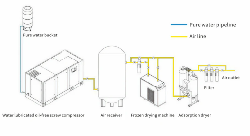
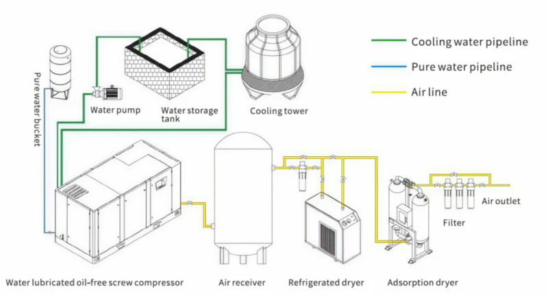
For high-capacity facilities or systems located in hot environments, Water-Cooled Compressor Models provide an exceptionally reliable thermal solution. These heavy-duty industrial platforms replace or supplement cooling fans with shell-and-tube liquid heat exchangers positioned directly along the cylinder walls and primary discharge lines. Cold water from an external cooling tower or chiller loop flows continuously through the heat exchanger, absorbing thermal energy far more effectively than air. This liquid cooling maintains consistent compressed air temperatures regardless of ambient weather conditions, extending the operational life of the zeolite beds and making water-cooled compressors the preferred choice for mission-critical industrial installations worldwide.
8. Maintenance Guide for Thermal Longevity & System Uptime
A certified oil-free compressor may pass all factory thermal audits when new, but maintaining that cool operating profile across years of field service requires strict adherence to a disciplined preventative maintenance schedule. As field dust and mechanical wear accumulate, cooling system efficiency can decline quickly if ignored.
Technical operators must be trained to recognize and resolve thermal anomalies quickly. For instance, if an inline thermistor registers a sudden, localized temperature spike while system pressures stay within normal targets, the internal discharge reed valves may have developed scale deposits or micro-cracks. A leaking reed valve allows hot compressed air to flow back into the cylinder cavity on the intake stroke, causing internal air recirculation that spikes temperatures quickly. Disassembling the valve plates and replacing worn reeds resolves the issue and restores full system uptime.
9. Economic & Environmental Return on Investment
Implementing a highly optimized thermal management framework requires a careful evaluation of initial capital costs versus long-term operational savings. While integrated aluminum fin configurations, dual cooling fan shrouds, and electronic NTC sensors add to upfront production costs, they deliver a strong return on investment (ROI) by maximizing machinery longevity and minimizing energy costs.
Minimizing Operational Expenditures: A compressor operating at cooler temperatures runs with higher volumetric efficiency, requiring less electrical energy to process each liter of gas. Over extended 24/7 duty cycles, this lower power draw translates into substantial electricity savings for hospitals and industrial plants. Furthermore, proper cooling prevents thermal degradation of sacrificial PTFE seals, doubling the lifespan of internal components and reducing the frequency of field maintenance service calls.
Protecting Downstream Assets: The most significant economic benefit of an optimized thermal management system is the protection it provides to the expensive downstream synthetic zeolite sieve beds. By cooling the compressed air stream before it reaches the desiccant towers, the system prevents thermal breakdown of the crystalline structures. This protection eliminates the risk of premature sieve bed degradation, avoiding costly emergency replacement procedures and ensuring continuous, high-purity oxygen delivery for your entire enterprise.
10. Ten In-Depth Frequently Asked Questions (FAQ)
A: This heat buildup follows the laws of adiabatic compression. When the advancing piston rapidly reduces the volume inside the cylinder, the work performed increases the internal kinetic energy of the gas molecules, concentrating them and causing an immediate rise in temperature.
A: High temperatures increase the kinetic energy of gas molecules, disrupting the electrostatic attraction that binds nitrogen to the zeolite crystals. If compressed air enters the PSA beds above 40°C, nitrogen escapes early, causing oxygen output purity to drop quickly.
A: Cooling fins significantly increase the external surface area of the aluminum housing. This expanded surface area allows passing ambient air currents to carry away conducted heat far more effectively than flat surfaces.
A: Fin arrays utilize tapered geometries with precisely calculated spacing. This design prevents airflow restrictions and ensures smooth forced convection currents can sweep through the fin channels continuously.
A: Mounting the fan directly onto the primary drive shaft means its rotation speed scales automatically with the motor. As the compressor runs faster and generates more heat under load, the fan spins faster to increase cooling airflow.
A: While PTFE features excellent self-lubricating properties, extreme heat above 120°C can cause the polymer compound to soften and deform. This alters the tight seal against the cylinder walls, allowing air leakage and reducing flow rates.
A: NTC thermistors continuously monitor head temperatures and feed a real-time signal to the device ECU. If temperatures exceed safe limits, the ECU can trigger warning alarms or ramp down motor speeds before a critical fault develops.
A: Positioned flush against the copper stator coils, this mechanical switch flexes and snaps its contacts open if winding temperatures hit a critical safety threshold, cutting power instantly to protect the motor from burning out.
A: Water-cooled compressors are preferred for high-capacity industrial plants or installations located in hot climates. Their liquid shell-and-tube heat exchangers remove heat far more effectively than air currents, maintaining stable temperatures regardless of ambient weather.
A: Technical operators should use dry compressed air weekly to blow out accumulated dust, lint, and field debris from the narrow gaps between the aluminum cooling fins, preserving optimal thermal dissipation.
Master Your System Thermal Budget Today
Stop allowing thermal surges to compromise your molecular sieves and battery runtimes. Partner with our engineering team to integrate high-efficiency oil-free compressors optimized for stable, continuous-duty performance.