
An advanced industrial exploration of mechanical attenuation, structural harmonics mitigation, fluid pulse attenuation, and acoustic barrier engineering in oil-free micro-pumps.
1. Introduction: The Acoustic Challenge in Critical Environments
In the field of medical device manufacturing and precision industrial gas generation, system performance is measured not only by chemical throughput and volumetric flow rate. Modern product development places immense value on human-centric design, institutional sound limits, and structural reliability. Within Pressure Swing Adsorption (PSA) oxygen concentration systems, managing noise pollution and mechanical vibration has evolved from a secondary packaging concern into a core engineering challenge. Because medical oxygen concentrators operate inside patient bedrooms, hospital recovery wards, intensive care units, and close laboratory environments, the continuous hum and tremor of mechanical subsystems can severely impact the surrounding space.
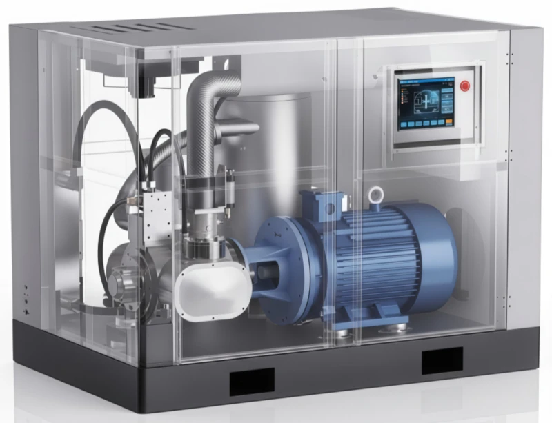
The primary source of sound emissions and kinetic energy transfers within any autonomous oxygen generation asset is the oil-free air compressor. By compacting ambient gas and injecting pressurized air into synthetic zeolite towers, the compressor operates under continuous stress. Without fluid oil films to cushion internal parts and absorb heat, oil-free micro-pumps are susceptible to raw mechanical vibrations, high-frequency piston ring friction, and intense pneumatic pulsations. Managing these complex acoustic energies requires a multi-tier engineering approach that addresses noise at the source, isolates structure-borne pathways, and creates high-performance external sound barriers.
For B2B buyers, medical device developers, and mechanical procurement specialists, interpreting supplier decibel ratings requires a clear understanding of acoustic physics and structural dynamics. A compressor that is rated low in “free-field” testing can become remarkably loud once bolted tightly inside a rigid sheet-metal equipment cabinet. This guide look into the physics of sound generation inside small oil-free pumps, explores advanced balancing counterweights, reviews intake and exhaust silencers, and establishes practical blueprints for isolating vibration to achieve ultra-quiet performance in medical-grade environments.
2. The Physics of Sound and Vibration in Oil-Free Pumps
To effectively minimize decibel outputs, design engineers must first map the specific root causes of mechanical noise inside miniature oil-free compressors. Acoustic emissions inside a standard rocking piston or diaphragm micro-pump can be broadly divided into three core categories: mechanical friction noise, primary structural imbalance forces, and fluid-induced pneumatic pressure pulsations.
Mechanical friction noise stems directly from the self-lubricating interfaces within the pump head. As a rocking piston compressor operates, the synthetic PTFE cup seal slides vertically and rocks laterally against the polished aluminum cylinder sleeve walls. This polymer-on-metal sliding action creates a continuous high-frequency acoustic signature. If the cylinder bore surface texture deviates even slightly from factory micro-tolerances, this sliding friction amplifies into a loud squeal. Additionally, the constant opening and closing of thin metal or PEEK flapper reed valves against their valve plates creates sharp, click-clack sounds that resonate through the cylinder head casting.
Structural vibration is generated by the reciprocating mass of the internal components. As the motor drive shaft turns, the eccentric crank pin forces the single-piece connecting rod and piston head up and down. This reciprocating mass creates strong alternating primary forces along the cylinder’s vertical centerline. Because the connecting rod rocks laterally, it also creates shifting secondary horizontal force vectors. If these moving masses are not precisely counterbalanced, they manifest as physical structural tremors that shake the entire pump housing. When the compressor is bolted directly to an equipment chassis, these tremors translate into structure-borne vibrations, transforming the device cabinet into a large acoustic speaker.
3. Structural Mass Balancing & Eccentric Crank Counterweights
Mitigating structure-borne tremors requires balancing the internal moving forces directly at the main drive axis. Sourcing engineers should inspect the internal configuration of the compressor’s crankshaft to ensure that the supplier has incorporated advanced mass-balancing techniques.
The primary countermeasure is installing a calculated eccentric crank counterweight. Because the piston head and connecting rod are offset from the true center of the motor shaft, a matching counter-mass must be cast or machined directly opposite the crank pin. This counterweight is strategically shaped so that its rotational centrifugal force opposes and cancels out the linear momentum of the reciprocating piston assembly. In dual-cylinder compressors, further balance is achieved by implementing a 180-degree phase offset between the pistons. This opposing movement means that as Cylinder A moves upward on its compression stroke, Cylinder B travels downward on its intake stroke, allowing their primary inertial masses to cancel each out dynamically.
Furthermore, premium micro-compressors often utilize heavy cast-steel flywheels integrated into the primary drive hub. The high rotational inertia of a heavy flywheel acts as a mechanical energy reservoir, dampening the rapid speed variations that occur as the piston passes through peak compression resistance. By smoothing out these torsional speed pulses, the flywheel minimizes torque ripple feedback into the motor bearings, extending bearing operational life and reducing low-frequency hums during grueling 24/7 continuous duty runs.
4. Advanced Intake and Exhaust Silencing Technologies
Fluid-induced noise represents the largest contributor to high-decibel environmental pollution from air pumps. Every time the intake valve opens, ambient air rushes into the cylinder cavity at high speed, creating a series of rapid air pulsations. When these pulsations exit the exhaust manifold under pressure, they form a loud, rhythmic roar. Managing these airborne fluid sound waves requires the installation of advanced silencing networks.
The primary attenuation technology is the porous labyrinth silencer. Integrated straight into the intake filter shell, a labyrinth silencer forces the incoming air to navigate through a twisted path lined with acoustic sound-absorptive foams or porous sintered polymers. As the sound waves reflect off these convoluted inner walls, their high-frequency peaks are scattered and absorbed, dropping the air intake noise level by up to 15 decibels without causing excessive airflow restriction that would starve the compressor head.
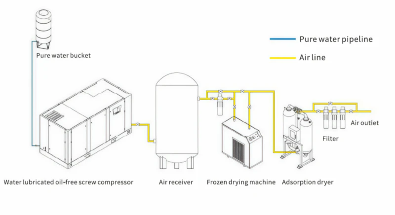
On the discharge line, fluid sound waves are managed by installing expansion chambers or pulsation dampeners. When compressed air exits the cylinder head, it travels in high-pressure pulses rather than a smooth, continuous stream. An expansion chamber increases the cross-sectional area of the pipeline, allowing the compressed air pulses to expand and dissipate their kinetic energy before continuing into the downstream filtration check-valves. This creates a smooth, continuous air delivery that optimizes PSA zeolite tower operation and prevents dangerous mechanical vibrations from rattling the facility plumbing.
5. Isolation Physics: Elastomer, Spring, and Silicone Suspensions
Even with perfect counterweight balancing and advanced flywheels, a micro-compressor will always pass a minor amount of physical vibration into its support frame. To prevent these residual structural tremors from migrating into the main machine housing, the compressor must be physically isolated from the chassis using high-performance suspension systems.
This structural isolation relies on the physics of spring-mass-damper dynamics. The compressor pump functions as the primary mass, while the flexible mounting supports act as the springs and dampers. Sourcing specifications should dictate the use of high-compliance elastomer or silicone gel mounting boots at every anchoring point. These specialized polymers are engineered with precise durometer (hardness) ratings tailored to the unique weight of the pump module. The soft suspension absorbs mechanical micro-movements, preventing vibration transmission into the enclosure sheet-metal panels, which would otherwise rattle and amplify the low-frequency hum.
Equally important is implementing flexible coupling links along the pneumatic and electrical paths. Connecting a vibrating compressor head to a rigid copper pipeline will stress the joints and cause the entire plumbing array to resonate loudly. To mitigate this risk, premium installations use reinforced silicone hoses or flexible braided polymer lines between the pump discharge port and the air filtration system. Electrical lines should be routed with generous service loops, ensuring that no wire is pulled taut, which could otherwise establish a bridge for mechanical energy transmission.
6. Enclosure Design, Labyrinth Airpaths, and Absorptive Insulation
The final line of defense against noise pollution is the design of the primary machine cabinet. When dealing with compact mobile devices or institutional stationary systems, enclosing the compressor within an airtight box is an effective way to block airborne decibels. However, this creates a significant engineering challenge: a compressor requires a constant influx of fresh ambient air to handle cooling loads and feed its suction intake.
To resolve this challenge, modern equipment cabinets use labyrinth cooling airpaths. Rather than cutting straight vent slots into the metal panels—which would allow sound waves to escape directly outside—the cabinet incorporates a series of overlapping internal baffles. Cooling air is forced to pass through a winding, S-shaped channel to reach the pump. The inner faces of these baffles are fully lined with high-density, open-cell acoustic insulation foam or specialized composite sound-barrier mats. As the internal sound waves strike the foam-lined channels, their kinetic energy is dissipated into heat, dropping noise levels significantly while maintaining proper cooling airflow.
The composition of the cabinet panels also plays a key role. Thin, single-ply sheet metal panels possess very low mass, allowing low-frequency vibrations to resonate and pass through into the surrounding room. Premium enclosures counteract this by utilizing heavy-gauge steel, reinforced polymers, or dual-ply damped laminate sheets. Applying viscoelastic dampening compounds directly to the interior panel surfaces alters their natural resonant frequency, preventing panel rattle and ensuring the device remains whisper-quiet throughout long-term operations.
7. Computational Modeling: CFD and FEA Engineering Simulations
Achieving sub-45 decibel operating limits without sacrificing volumetric flow requires advanced engineering simulation tools during the early phases of design. Modern compressor manufacturers utilize Finite Element Analysis (FEA) and Computational Fluid Dynamics (CFD) software to identify and eliminate acoustic risks before manufacturing structural components.
FEA software is used to model the structural harmonics of the entire compressor assembly. By entering the precise tensile and elastic properties of the aluminum chassis and polymer mounts, engineers can simulate the structural vibrations generated at different motor speeds. The software maps the system’s natural frequencies, allowing designers to reinforce weak frame points and ensure the pump’s operational speed never aligns with structural resonance zones, which would otherwise cause massive structural vibrations.
Simultaneously, CFD software models the fluid dynamics of the gas stream moving through the intake flapper valves and internal head passages. The software tracks localized pressure differentials, turbulent vortex formatting, and air-velocity spikes. This allows engineers to shape internal paths smoothly, minimizing air turbulence and fluid friction noise while optimizing volumetric efficiency to feed the downstream PSA towers with maximum flow rates.
8. Maintenance Routines for Acoustic Performance Longevity
A miniature compressor may pass factory noise inspections when brand new, but maintaining that ultra-quiet signature over thousands of hours of field service requires strict adherence to a disciplined preventive maintenance program. As components wear, clearances alter, which can cause decibel levels to climb quickly if ignored.
9. B2B Technical Diagnostics Manual for Vibration Anomalies
Technical operators must monitor acoustic signatures closely to identify and correct system variances before they cause component damage or downstream operational delays.
Symptom A: High-Frequency Metallic Ringing coming from the Pump Housing
This ringing sound indicates that the internal reed flapper valves have fatigued or developed scale deposits along their seats. When a valve reed fails to seat flush, air leaks backward during the compression cycle, creating a sharp whistling or metal-clattering noise. Disassemble the valve plate, clean the seat surfaces, and replace worn reeds with OEM parts to instantly restore quiet operation.
Symptom B: Intense Low-Frequency Rattle Passing through Cabinet Framework
This vibration pattern indicates that a primary elastomer mounting boot has ruptured or a structural screw has backed out under stress. When a mount fails, the compressor frame strikes the metal floor plates directly, causing loud structural rattles. Tighten all hardware to specified torque values and replace damaged elastomer mounts to isolate the pump completely.
Symptom C: Rhythmic Pumping Knock accompanied by Decreased Pressure
This deep knock typically points to a failing dual-eccentric motor bearing. If a bearing undergoes internal tracking wear, the main crankshaft tilts slightly out of alignment, causing the piston rod assembly to track unevenly and strike the head casting walls. Turn off power immediately to avoid motor winding destruction, and replace the eccentric bearing hub to re-align the mechanical drive axis.

10. Frequently Asked Questions (FAQ)
A: Internal sound emissions are driven by three main factors: high-frequency sliding friction between the polymer cup seal and the cylinder wall, primary and secondary structural imbalances from reciprocating masses, and pneumatic fluid pulsations from the intake and discharge air valves.
A: The counterweight is positioned opposite the crank pin on the drive shaft, matching the mass profile of the piston rod. Its rotational centrifugal force opposes and balances out the linear momentum of the piston head, minimizing structural tremors.
A: A heavy flywheel stores kinetic energy, acting as a rotational damper that smooths out speed variations caused by peak compression resistance. This minimizes torque ripple feedback into the motor bearings, reducing low-frequency humming noises.
A: Labyrinth mufflers force incoming air through a winding path lined with porous sound-absorptive foams. This scatters and dampens high-frequency sound waves from the flapper valves while maintaining ample cross-sectional area to support airflow.
A: Rigid metal lines act as acoustic bridges, carrying mechanical vibrations straight into the facility plumbing and causing system frames to resonate loudly. Flexible silicone or braided polymer lines absorb these micro-movements, ensuring quiet operation.
A: These boots act as soft spring-dampers tailored to the weight of the pump module. They absorb mechanical tremors before they can pass into sheet-metal cabinet panels, which would otherwise rattle and amplify low-frequency noise.
A: Cutting straight air vents allows internal pump noise to escape directly outside. A labyrinth airpath forces cooling air through a foam-lined, winding channel, absorbing acoustic energy while maintaining proper cooling airflow.
A: Polyetheretherketone (PEEK) flappers have lower mass and better damping properties than metal reeds. They respond quickly to pressure shifts and minimize high-frequency clicking sounds when striking the valve seat.
A: Over time, constant heat and mechanical stress can cause elastomer suspension mounts to dry out and harden. Once they lose their flexibility, structural vibrations pass directly into the cabinet, increasing low-frequency noise levels.
A: Valve failure typically manifests as a high-frequency whistling sound accompanied by low pressure output. Disassemble the cylinder head to check for structural cracks, scale deposits, or rust along the reed tabs.
Partner with an Acoustic Engineering Pioneer
Stop gambling your medical system reliability on unverified micro-pumps. Reach out to our B2B procurement division to configure a certified oil-free miniature compressor that matches your exact pneumatic curves and regulatory benchmarks.