
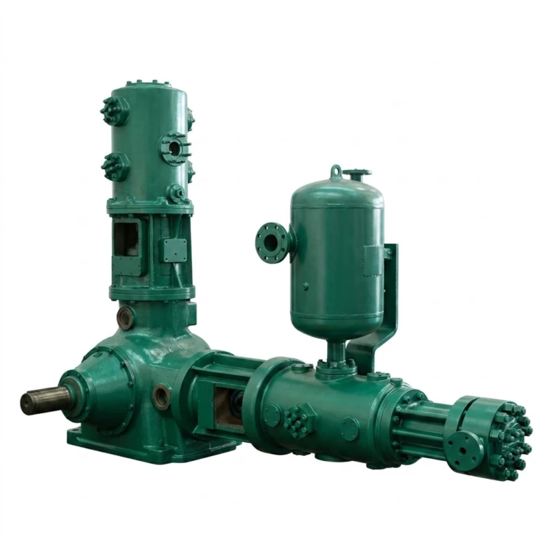
Hydrogen Compressor — Oil-Free Reciprocating Piston Series
Oil-Free Reciprocating Piston Compressor for Hydrogen and Hydrogen-Containing Gas Streams · Discharge Pressure 0.20–6.0 MPa · Flow 0.1–100 m³/min · 7.5–2000 kW · 63 Standard Models
The hydrogen compressor is an oil-free reciprocating piston compression system purpose-built for the unique physical, chemical, and safety requirements of hydrogen gas (H₂) and hydrogen-rich process streams. Hydrogen is the lightest gas — approximately 14 times lighter than air — and presents extreme leakage risk through conventional shaft seals and piston ring clearances that are acceptable in heavier gas compressors. It forms flammable mixtures with air across a very wide concentration range of 4% to 75% by volume. Its small molecular diameter causes hydrogen embrittlement of certain steels and rapid permeation through polymer seals rated for other gases. It burns with an invisible flame, making leakage-initiated fires extremely difficult to detect. All of these properties demand dedicated hydrogen compressor design that cannot be achieved by modifying an air compressor or a standard gas compressor.
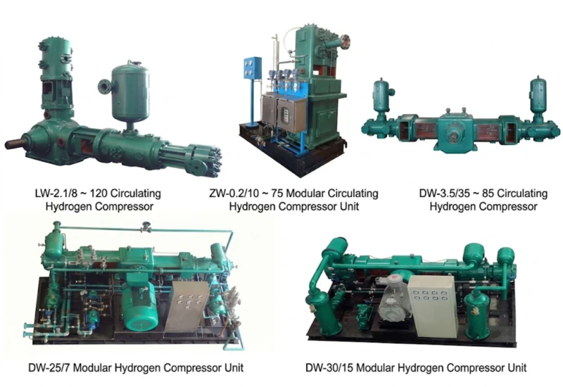
This series covers 63 standard models with flow from 0.1 m³/min to 100 m³/min at discharge pressures of 0.20 to 6.0 MPa. Inlet conditions span from micro-positive-pressure (near-atmospheric) for hydrogen production and recovery applications to high-pressure inlets (0.04 to 2.40 MPa) for booster compression stages. Mechanical configurations include twin-column single-stage (Twin-col. single-stage), twin-column two-stage (Twin-col. two-stage), twin-column three-stage (Twin-col. 3-stage), twin-column four-stage (Twin-col. four-stage), and four-column four-stage (Four-col. four-stage) arrangements matched to the specific pressure ratio and flow range of each application. Drive power ranges from 7.5 kW to 2,000 kW with voltage options of 380 V, 6 kV, and 10 kV. Custom single-unit capacity within 5.5 kW to 2,000 kW available on request for both oil-free hydrogen compressors and hydrogen booster compressors.
All models use oil-free PTFE composite piston rings with hydrogen-service distance piece isolation, hydrogen-specific labyrinth shaft seals or double mechanical seals with purge gas, hydrogen-compatible elastomers and gasket materials, micro-positive-pressure or controlled inlet design to prevent air ingress, explosion-proof electrical equipment, and stainless steel or hydrogen-service alloy valve and seal components. Proven in chlor-alkali electrolysis hydrogen recovery, water electrolysis hydrogen filling stations, petroleum refinery hydroprocessing, methanol and ammonia synthesis feed, hydrogen fuel cell vehicle fuelling stations, and hydrogen energy storage installations.
0.20–6.0 MPa
0.1–100 m³/min
63 Standard Models
7.5–2000 kW
380 V / 6 kV / 10 kV
Explosion-Proof Motors
High-Pressure Inlet Options
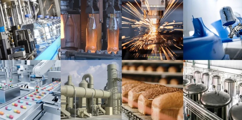
Typical applications: Chlor-alkali electrolysis hydrogen recovery and compression · Water electrolysis green hydrogen production · Petroleum refinery hydroprocessing feed · Methanol and ammonia synthesis hydrogen feed · Hydrogen fuel cell vehicle (FCEV) fuelling stations · Hydrogen energy storage compression · Semiconductor fab hydrogen supply · Petrochemical hydrogenation reactors · Edible oil hydrogenation · Steel plant hydrogen annealing furnaces · Glass plant hydrogen atmosphere furnaces · Syngas hydrogen fraction compression
Technical Parameters — Full Model Range (63 Models)
Oil-Free Hydrogen Compressor and Hydrogen Booster Compressor · Discharge Pressure 0.20–6.0 MPa · Flow 0.1–100 m³/min
Flow is stated in m³/min at inlet conditions. Inlet condition notation: “micro-positive-pressure” indicates near-atmospheric inlet design preventing air ingress; bracketed pressures e.g. “(inlet 2.10 MPa)” indicate high-pressure booster inlet configurations where hydrogen is received at the specified inlet pressure from an upstream stage or vessel. Stage count (single-stage / two-stage / three-stage / four-stage) is selected based on the overall pressure ratio required. Custom single-unit capacity within 5.5 kW to 2,000 kW available on request for oil-free hydrogen compressors and hydrogen booster compressors.
| No. | Model | Pattern | Flow (m³/min) | Inlet Condition | Discharge (MPa) | Dimensions L×W×H (mm) | Weight (t) | Power (kW) | Voltage (V) |
|---|---|---|---|---|---|---|---|---|---|
| 1 | ZW-0.1/21~25 | Twin-col. two-stage | 0.1 | Inlet 2.10 MPa | 2.50 | 720×763×1640 | 0.80 | 7.5 | 380 |
| 2 | ZW-0.25/13~24 | Twin-col. two-stage | 0.25 | Inlet 1.30 MPa | 2.40 | 1550×985×2013 | 1.00 | 11 | 380 |
| 3 | ZW-1.1/11.5~24.5 | Twin-col. two-stage | 1.1 | Inlet 1.15 MPa | 2.45 | 2495×1800×2945 | 1.80 | 37 | 380 |
| 4 | ZW-1.1/25 | Twin-col. 3-stage | 1.1 | Micro-positive-P | 2.50 | 1550×1340×1910 | 2.83 | 30 | 380 |
| 5 | ZW-1.5/8 | Twin-col. single-stage | 1.5 | Micro-positive-P | 0.80 | 720×763×1274 | 0.58 | 15 | 380 |
| 6 | ZW-1.5/25 | Twin-col. 3-stage | 1.5 | Micro-positive-P | 2.50 | 1550×1340×1910 | 3.00 | 30 | 380 |
| 7 | ZW-2/4 | Twin-col. two-stage | 2 | Micro-positive-P | 0.40 | 1520×800×1360 | 0.58 | 15 | 380 |
| 8 | ZW-2/11 | Twin-col. two-stage | 2 | Micro-positive-P | 1.10 | 720×763×1475 | 0.80 | 18.5 | 380 |
| 9 | ZW-3/7 | Twin-col. two-stage | 3 | Micro-positive-P | 0.70 | 1520×800×1360 | 0.58 | 22 | 380 |
| 10 | ZW-3.5/0.2~8.6 | Twin-col. two-stage | 3.5 | Inlet 0.02 MPa | 0.86 | 2250×1296×2200 | 2.00 | 30 | 380 |
| 11 | ZW-3/30 | Twin-col. 3-stage | 3 | Micro-positive-P | 3.00 | 1920×1900×2825 | 3.50 | 45 | 380 |
| 12 | ZW-4/8 | Twin-col. two-stage | 4 | Micro-positive-P | 0.80 | 2250×1296×2200 | 2.00 | 30 | 380 |
| 13 | ZW-6/8 | Twin-col. two-stage | 6 | Micro-positive-P | 0.80 | 2250×1296×2200 | 2.10 | 45 | 380 |
| 14 | 3ZW-6/30 | Twin-col. 3-stage | 6 | Micro-positive-P | 3.00 | 1845×1660×2360 | 3.00 | 75 | 380 |
| 15 | 3ZW-8/20 | Twin-col. 3-stage | 8 | Micro-positive-P | 2.00 | 1845×1660×2360 | 3.00 | 75 | 380 |
| 16 | 3ZW-9.5/30 | Twin-col. 3-stage | 9.5 | Micro-positive-P | 3.00 | 1845×1660×2360 | 3.50 | 110 | 380 |
| 17 | ZW-13/30 | Twin-col. 3-stage | 13 | Micro-positive-P | 3.00 | 2764×2000×3277 | 6.00 | 160 | 380 |
| 18 | ZW-15/8 | Twin-col. two-stage | 15 | Micro-positive-P | 0.80 | 2300×1800×2800 | 5.00 | 132 | 380 |
| 19 | LW-2.1/8~120 | Twin-col. 3-stage | 2.1 | Inlet 0.80 MPa | 12.00 | 3200×1685×2430 | 6.50 | 160 | 380 |
| 20 | LW-4.65/24~35 | Twin-col. single-stage | 4.65 | Inlet 2.40 MPa | 3.50 | 2400×1550×2350 | 4.50 | 185 | 380 |
| 21 | LW-5.6/0.4~8.1 | Twin-col. two-stage | 5.6 | Inlet 0.04 MPa | 0.81 | 2250×1400×2200 | 3.50 | 55 | 380 |
| 22 | LW-6/15 | Twin-col. two-stage | 6 | Micro-positive-P | 1.50 | 2280×950×2170 | 1.80 | 65 | 380 |
| 23 | LW-9/3.5~34 | Twin-col. two-stage | 9 | Inlet 0.35 MPa | 3.40 | 3200×1685×2430 | 6.50 | 250 | 380 |
| 24 | LW-10/4 | Twin-col. single-stage | 10 | Micro-positive-P | 0.40 | 2340×910×2070 | 1.80 | 55 | 380 |
| 25 | LW-11.7/0.6~10 | Twin-col. two-stage | 11.7 | Inlet 0.06 MPa | 1.00 | 2625×1550×2576 | 3.00 | 132 | 380 |
| 26 | LW-20/2 | Twin-col. single-stage | 20 | Micro-positive-P | 0.20 | 2150×910×2170 | 2.00 | 65 | 380 |
| 27 | LW-20/4 | Twin-col. two-stage | 20 | Micro-positive-P | 0.40 | 2730×1550×2432 | 3.00 | 110 | 380 |
| 28 | LW-20/8 | Twin-col. two-stage | 20 | Micro-positive-P | 0.80 | 2630×1550×2332 | 3.00 | 132 | 380 |
| 29 | LW-20/18 | Twin-col. 3-stage | 20 | Micro-positive-P | 1.80 | 3500×2600×1850 | 6.00 | 240 (250) | 380/6K/10K |
| 30 | LW-25/3.5 | Twin-col. single-stage | 25 | Micro-positive-P | 0.35 | 2926×1550×2690 | 3.20 | 132 | 380 |
| 31 | LW-30/2 | Twin-col. single-stage | 30 | Micro-positive-P | 0.20 | 3140×1550×2445 | 3.40 | 90 | 380 |
| 32 | LW-30/4 | Twin-col. two-stage | 30 | Micro-positive-P | 0.40 | 2990×2370×1550 | 4.00 | 132 | 380 |
| 33 | LW-34.2/16 | Twin-col. two-stage | 34.2 | Micro-positive-P | 1.60 | 3500×1600×1850 | 9.00 | 350 | 380/6K/10K |
| 34 | LW-35/0.3~3.5 | Twin-col. two-stage | 35 | Inlet 0.03 MPa | 0.35 | 2365×1600×2310 | 4.20 | 132 | 380 |
| 35 | LW-40/2 | Twin-col. single-stage | 40 | Micro-positive-P | 0.20 | 2926×1550×2690 | 3.20 | 132 | 380 |
| 36 | LW-40/4 | Twin-col. two-stage | 40 | Micro-positive-P | 0.40 | 2360×1655×2548 | 4.50 | 160 | 380 |
| 37 | LW-50/6 | Twin-col. two-stage | 50 | Micro-positive-P | 0.60 | 2360×1685×2235 | 6.50 | 260 | 380/6K/10K |
| 38 | LW-60/2.5 | Twin-col. single-stage | 60 | Micro-positive-P | 0.25 | 3260×1655×2548 | 5.00 | 220 | 380 |
| 39 | LW-60/4 | Twin-col. two-stage | 60 | Micro-positive-P | 0.40 | 3260×1655×2548 | 5.00 | 260 | 380/6K/10K |
| 40 | LW-75/1.5 | Twin-col. single-stage | 75 | Micro-positive-P | 0.15 | 4000×2100×2600 | 7.80 | 220 | 380 |
| 41 | DW-5/0.08~120 | Four-col. four-stage | 5 | Inlet 0.08 MPa | 12.00 | 5000×4500×2200 | 6.50 | 132 | 380 |
| 42 | DW-6.8/60 | Twin-col. four-stage | 6.8 | Micro-positive-P | 6.00 | 4850×2500×1000 | 5.50 | 160 | 380 |
| 43 | DW-8.5/45 | Twin-col. four-stage | 8.5 | Micro-positive-P | 4.50 | 4850×2500×1000 | 5.50 | 160 | 380 |
| 44 | DW-10/24~36 | Twin-col. single-stage | 10 | Inlet 2.40 MPa | 3.60 | 4900×3300×2500 | 10.00 | 355 | 6K/10K |
| 45 | DW-11.5/12 | Twin-col. two-stage | 11.5 | Micro-positive-P | 1.20 | 5200×1700×2200 | 6.50 | 132 | 380 |
| 46 | DW-15/8 | Twin-col. two-stage | 15 | Micro-positive-P | 0.80 | 5200×1700×2200 | 6.10 | 132 | 380/6K/10K |
| 47 | DW-20/8 | Twin-col. two-stage | 20 | Micro-positive-P | 0.80 | 5200×1700×2200 | 6.50 | 160 | 380 |
| 48 | DW-22/0.4~16 | Twin-col. 3-stage | 22 | Inlet 0.04 MPa | 1.60 | 5000×1450×2400 | 7.00 | 280 | 380/6K/10K |
| 49 | DW-27/11~15.8 | Twin-col. single-stage | 27 | Inlet 1.10 MPa | 1.58 | 5100×3700×2520 | 9.00 | 315 | 380/6K/10K |
| 50 | DW-27.5/5~8 | Twin-col. single-stage | 27.5 | Inlet 0.50 MPa | 0.80 | 5200×1700×2200 | 7.00 | 220 | 380/6K/10K |
| 51 | DW-34.2/16 | Twin-col. two-stage | 34.2 | Micro-positive-P | 1.60 | 5200×1700×2200 | 9.00 | 315 | 3380/6K/10K |
| 52 | DW-35/8 | Twin-col. two-stage | 35 | Micro-positive-P | 0.80 | 5200×1700×2200 | 7.00 | 250 | 380/6K/10K |
| 53 | DW-35/40 | Four-col. four-stage | 35 | Micro-positive-P | 4.00 | 6200×3300×2500 | 12.00 | 500 | 6K/10K |
| 54 | DW-40/2~3.5 | Twin-col. single-stage | 40 | Inlet 0.20 MPa | 0.35 | 4760×2045×2105 | 5.50 | 160 | 380 |
| 55 | DW-40/8 | Twin-col. two-stage | 40 | Micro-positive-P | 0.80 | 5200×1700×2200 | 7.50 | 280 | 380/6K/10K |
| 56 | DW-51.5/6 | Twin-col. two-stage | 51.5 | Micro-positive-P | 0.60 | 4880×3000×2265 | 6.00 | 280 | 380/6K/10K |
| 57 | DW-57.5/4.5 | Twin-col. two-stage | 57.5 | Micro-positive-P | 0.45 | 5000×1450×3100 | 6.00 | 315 | 6K/10K |
| 58 | DW-60/6 | Twin-col. two-stage | 60 | Micro-positive-P | 0.60 | 5000×1450×3100 | 7.00 | 350 | 6K/10K |
| 59 | DW-66/28 | Four-col. four-stage | 66 | Micro-positive-P | 2.80 | 5800×3300×2500 | 13.00 | 900 | 6K/10K |
| 60 | DW-68/4 | Twin-col. two-stage | 68 | Micro-positive-P | 0.40 | 5000×1450×3100 | 7.00 | 400 | 6K/10K |
| 61 | DW-86/4~12.5 | Twin-col. single-stage | 86 | Inlet 0.40 MPa | 1.25 | 7000×4200×3100 | 25.00 | 1400 | 6K/0K |
| 62 | DW-92/5~13 | Twin-col. single-stage | 92 | Inlet 0.50 MPa | 1.30 | 7000×4200×3100 | 25.00 | 1500 | 6K/10K |
| 63 | DW-100/8 | Twin-col. two-stage | 100 | Micro-positive-P | 0.80 | 5600×3600×2550 | 17.00 | 630 | 6K/10K |
Note: “Micro-positive-P” inlet indicates near-atmospheric micro-positive-pressure inlet design preventing air ingress. Bracketed inlet pressures indicate high-pressure booster configurations where hydrogen is received from an upstream stage or storage vessel. Custom single-unit capacity within 5.5 kW to 2,000 kW available on request for both oil-free hydrogen compressors and hydrogen booster compressors. All 380 V models use explosion-proof motors; models at 6 kV and 10 kV use flame-proof or increased-safety motors.
Why Hydrogen Requires Dedicated Oil-Free Compression Equipment
The Unique Physical and Chemical Properties of Hydrogen
Hydrogen gas presents a combination of properties that make it the most demanding gas to compress safely. Its molecules are the smallest of any gas — approximately 1/14 the molecular weight of air — which means hydrogen permeates through polymer seals, diffuses through metal lattices, and leaks through clearances that are effectively gas-tight for all other gases. Standard air compressor shaft seals and piston ring clearances, designed for air molecules of molecular weight 29, allow substantial hydrogen leakage that creates localised flammable concentrations outside the compressor. Hydrogen also burns with an invisible flame at a very wide flammability range of 4% to 75% in air — a leakage-initiated fire can be undetectable without specific hydrogen leak detection equipment, making seal integrity not merely an efficiency concern but a critical safety requirement.
Hydrogen causes embrittlement of certain carbon and alloy steels at elevated pressure — this hydrogen embrittlement reduces the tensile ductility of the steel, increasing the risk of sudden fracture of pressure-containing components without visible prior deformation. All pressure-containing components in this series — cylinder bodies, valve housings, inter-stage piping, and piston rods — use hydrogen-service-rated materials selected and tested in accordance with Nelson curve criteria for the operating temperature and hydrogen partial pressure of each stage. The oil-free design using PTFE composite piston rings is equally essential: lubricating oil contamination of compressed hydrogen causes fouling of downstream process equipment in chemical synthesis applications and catalyst poisoning in hydroprocessing reactors, and oil vapour in hydrogen creates a combustible aerosol mixture in high-pressure piping that is more hazardous than hydrogen alone.
Stage Count Selection — Matching Pressure Ratio to Compression Stages
Because hydrogen has an unusually high isentropic exponent (approximately 1.4, similar to air but with much higher discharge temperature per unit pressure ratio due to the high specific heat ratio of hydrogen at low molecular weight), the discharge temperature rise per compression stage is more severe than for heavier gases at the same pressure ratio. To maintain discharge temperature below safe limits — typically 160 deg C maximum per stage — and to achieve adequate volumetric efficiency at each stage, the compression ratio per stage for hydrogen is limited to approximately 2.5:1 to 3.5:1. This means that to achieve a 30:1 overall pressure ratio (from near-atmospheric to 3.0 MPa), three compression stages are required. For higher pressure ratios to 6.0 MPa or above from atmospheric inlet, four stages are standard. Models with elevated inlet pressure (booster compressors) can achieve the required outlet pressure in fewer stages because the overall pressure ratio from inlet to outlet is lower.
High-Pressure Inlet Booster Models
Several models in this series are booster compressors with elevated inlet pressures — for example the ZW-0.1/21~25 (inlet 2.10 MPa, outlet 2.50 MPa) and LW-4.65/24~35 (inlet 2.40 MPa, outlet 3.50 MPa). These are used where hydrogen arrives from an upstream source already at moderate pressure — such as from a reforming unit, an electrolyser stack at working pressure, or a storage vessel being discharged — and must be boosted to a higher pressure for pipeline injection, cylinder filling, or process feed at higher pressure. Booster compressors have smaller bore-to-stroke ratios reflecting their lower volumetric flow requirement per unit mass throughput at the elevated inlet density of hydrogen, and their shaft seal design must handle the higher inlet pressure without leakage even under transient pressure fluctuations.
5 Core Advantages of This Hydrogen Compressor Series
Intrinsically Oil-Free — Hydrogen-Grade Purity
PTFE composite piston rings with distance piece isolation between crankcase and compression cylinder deliver hydrogen free of hydrocarbon contamination at every stage. No downstream oil coalescer or activated-carbon stage is needed for oil removal — the hydrogen leaving the compressor contains no lubricating oil by design. This is the mandatory standard for refinery hydroprocessing catalyst protection, ammonia and methanol synthesis catalyst protection, fuel cell vehicle hydrogen purity compliance, and semiconductor hydrogen supply applications.
Broadest Hydrogen Coverage — 63 Models
From a 7.5 kW small booster compressor for laboratory hydrogen supply to a 1,500 kW large-capacity single-stage booster for refinery hydrogen make-up, 63 standard models cover every industrial hydrogen compression requirement in a single product family. The unified oil-free design philosophy, explosion-proof electrical equipment standard, and hydrogen-service material specification apply across the entire range, simplifying specification and supplier qualification regardless of application scale.
Hydrogen-Specific Sealing — Zero Leakage Architecture
All shaft seals are designed specifically for hydrogen service — using labyrinth seals with inert purge gas sweep or double mechanical seals with seal gas barrier — to prevent hydrogen leakage regardless of the small molecular diameter. Piston rod packings use hydrogen-service PTFE segmented rings with controlled leakage collection to a safe recovery point. Every sealing interface is verified for hydrogen service at both design pressure and thermal cycling conditions, not just at standard gas service conditions.
Flexible Inlet Pressure — Booster and From-Atmospheric Designs
The series covers both from-atmospheric (micro-positive-pressure inlet) and booster (elevated inlet pressure) configurations. This allows the correct compressor to be matched to the actual hydrogen source pressure — from electrolysis stacks operating at near-atmospheric through to reformer hydrogen at 2.0 to 2.5 MPa — without oversizing the compressor for a high overall pressure ratio when the hydrogen arrives already partially compressed. Booster models achieve better efficiency and lower equipment cost for high-inlet-pressure hydrogen sources.
Field-Maintainable with Hydrogen-Service Validated Spares
PTFE piston rings, valve plates and springs in hydrogen-service alloy, piston rod packings, and shaft seals are all field-replaceable items validated for hydrogen service. Maintenance in a hydrogen environment requires hydrogen-specific procedures — purging with inert gas before opening, controlled atmosphere for piston ring replacement to prevent air ingress, and hydrogen leak testing after reassembly before restart. Our application engineers provide model-specific hydrogen service maintenance procedures alongside the standard technical documentation.
Typical Application Scenarios
Chlor-Alkali Electrolysis Hydrogen Recovery
Chlorine-alkali electrolysis plants produce hydrogen as a co-product from the electrolysis of sodium chloride brine. This hydrogen is generated at near-atmospheric pressure, slightly above 0.1 MPa, and must be compressed for either sale as chemical hydrogen, use in on-site HCl synthesis, or pipeline transport to adjacent chemical plant users. Series models in the ZW and LW range with micro-positive-pressure inlet at 0.20 to 1.0 MPa discharge serve chlor-alkali hydrogen recovery stations, with oil-free construction mandatory because lubricant contamination of chlor-alkali hydrogen is unacceptable for downstream chemical process use.
ZW-1.5/8 to LW-20/8 · 1.5–20 m³/min · 0.40–0.80 MPa
Green Hydrogen from Water Electrolysis
Water electrolysis — both alkaline and PEM (proton exchange membrane) — produces hydrogen at near-atmospheric or low pressure (typically 0.1 to 1.0 MPa from PEM stacks). This hydrogen must be compressed for storage in high-pressure vessels (20 to 70 MPa for hydrogen fuel cell vehicle fuelling), pipeline distribution, or chemical feedstock use. The multi-stage models including DW-6.8/60 (four-stage to 6.0 MPa) and DW-5/0.08~120 (four-stage to 12.0 MPa from 0.08 MPa inlet) serve the first stage of high-pressure hydrogen storage compression at green hydrogen production sites, with additional reciprocating or diaphragm boosters for final stage compression to storage pressure.
ZW-3/30 to DW-35/40 · 3–35 m³/min · 3.0–6.0 MPa
Petroleum Refinery Hydroprocessing
Hydrodesulfurisation (HDS), hydrodenitrogenation (HDN), hydrocracking, and catalytic reforming hydrogen recycle circuits all require large volumes of high-purity hydrogen compressed to reactor operating pressures of 1.0 to 6.0 MPa. Hydrogen make-up compressors receive fresh hydrogen from a hydrogen production unit (steam methane reforming or electrolysis) at 1.0 to 2.5 MPa and boost it to reactor pressure. The high-inlet-pressure booster models — DW-27/11~15.8, DW-27.5/5~8, DW-86/4~12.5, DW-92/5~13 — serve refinery hydrogen make-up compression duty with single-stage booster configuration suited to the modest pressure boost ratio required.
DW-27/11 to DW-92/5~13 · 27–92 m³/min · Booster duty
Methanol and Ammonia Synthesis Feed
Methanol synthesis requires hydrogen-CO mixtures at 5.0 to 6.0 MPa reactor inlet pressure. Ammonia synthesis requires hydrogen-nitrogen mixtures at 15 to 30 MPa (with downstream reciprocating synthesis gas compressors for final pressure). The hydrogen feed compression stage — from reformer outlet at 1.0 to 2.5 MPa to synthesis loop pressure — is the primary application for the large LW and DW three-stage and four-stage models. These applications require strict oil-free hydrogen purity to protect synthesis catalysts from deactivation by hydrocarbon contamination, which is irreversible for precious-metal catalysts.
LW-20/18 to DW-66/28 · 20–66 m³/min · 1.80–3.0 MPa
Hydrogen Fuelling Stations for FCEVs
Hydrogen fuel cell vehicle fuelling stations require hydrogen compressed to 35 MPa or 70 MPa for vehicle tank filling. The first compression stage from hydrogen supply pipeline (typically 2 to 5 MPa) or on-site electrolyser (0.5 to 2 MPa) to intermediate storage (20 MPa) is within the range of this reciprocating series. Models with 6 MPa discharge (DW-6.8/60, DW-8.5/45) and four-stage models serve as the primary compressor stage in FCEV station compression trains, with ionic or diaphragm compressors providing the final stage to 70 MPa. Fuelling station hydrogen purity must meet SAE J2719 / ISO 14687 hydrogen quality standards, requiring oil-free compression throughout.
DW-6.8/60, DW-8.5/45, DW-35/40 · 6.0 MPa first stage
Industrial Atmosphere Furnaces and Chemical Hydrogenation
Steel annealing furnaces, copper bright annealing lines, glass polishing furnaces, and powder metallurgy sintering furnaces use hydrogen or hydrogen-nitrogen mixed atmospheres at 0.20 to 1.0 MPa to prevent oxidation and achieve controlled surface chemistry. These applications require a steady low-pressure hydrogen supply at modest flow rates from cylinders or pipeline. The LW-series single-stage models (LW-10/4 to LW-40/4) serve atmosphere furnace hydrogen supply compression. For chemical hydrogenation of edible oils, pharmaceuticals, or petrochemicals, higher purity and higher pressure hydrogen at 0.5 to 3.0 MPa is required from DW two-stage or three-stage models.
LW-10/4 to LW-40/4 · 0.20–0.40 MPa furnace atmosphere supply
Installed at Customer Sites
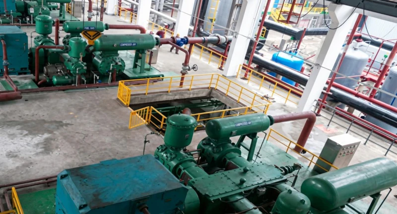
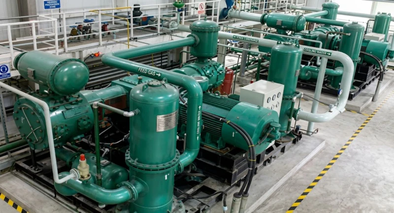
Oil-free hydrogen compressors from this series are operating in chlor-alkali plants, water electrolysis hydrogen production facilities, petroleum refineries, methanol synthesis plants, and hydrogen fuelling stations. The following images show representative customer site installations.
How to Specify a Hydrogen Compressor — Key Selection Criteria
Define Inlet Pressure and Hydrogen Source
The inlet pressure determines whether you need a from-atmospheric model (micro-positive-pressure inlet) or a booster model (elevated inlet pressure). Chlor-alkali electrolysis and water electrolysis hydrogen arrives near atmospheric pressure. Reformer hydrogen typically arrives at 1.0 to 2.5 MPa. Pipeline hydrogen arrives at supply pipeline pressure. Matching the compressor inlet to the actual source pressure, rather than specifying a from-atmospheric model that then throttles a high-pressure source, is critical for both efficiency and compressor longevity — operating a micro-positive-pressure model on a high-pressure inlet causes severe volumetric overload and discharge temperature problems.
Verify Hydrogen Purity Requirements and Impurities
While all models in this series are oil-free, the hydrogen may contain other impurities from the source — moisture from electrolysis, trace oxygen from PEM electrolyser crossover, CO from reformers, or H₂S from coke oven gas hydrogen fractions. These impurities affect material selection for valves, seals, and inter-stage coolers. Moisture requires stainless steel inter-stage coolers and separators. CO at high concentration requires CO-resistant sealing materials. Oxygen traces in hydrogen from PEM electrolysers must be removed before compression to prevent formation of explosive H₂-O₂ mixtures in the compression system. Always provide the full hydrogen composition and impurity analysis to our application engineers before specification.
Plan Hydrogen Safety Systems
Hydrogen compressor rooms require dedicated hydrogen leak detection systems — electrochemical or catalytic hydrogen sensors at ceiling level (hydrogen rises rapidly), with alarms at 10% LEL (lower explosive limit) and automatic compressor shutdown at 25% LEL. Emergency ventilation must provide minimum 12 air changes per hour with natural or forced ventilation direct to atmosphere. All electrical equipment must be rated for the hazardous area zone classification. Piping and fittings must use hydrogen-service ratings — standard stainless steel NPT fittings are not acceptable for hydrogen service above 0.7 MPa. Purge sequences with inert gas (nitrogen) for start-up and shutdown must be included in the operating procedure to prevent air-hydrogen mixing in the compression system.
Plan Downstream Treatment and Pressure Vessel Codes
Downstream of the compressor, install: inter-stage and final-stage moisture separators with automatic drains; a hydrogen-service high-pressure air receiver or buffer vessel sized for the process; pressure relief valves with discharge to a hydrogen flare or safe outdoor vent (not indoors); and pressure regulators for downstream distribution. All pressure vessels, piping, valves, and fittings in hydrogen service must be designed and certified under the applicable national pressure vessel code (GB150 in China, ASME VIII Div.1 for export to the USA, PED for Europe). Our documentation package for each compressor includes the required design pressure certificate data for vessel code compliance by the project pressure vessel engineer.
Frequently Asked Questions — Hydrogen Compressor
Ready to Specify an Oil-Free Hydrogen Compressor for Your Application?
Our application engineering team provides free hydrogen compressor sizing — including stage count optimisation for your pressure ratio, hydrogen purity specification review, booster versus from-atmospheric configuration recommendation, hydrogen safety system guidance, and complete technical documentation for regulatory approval. Factory-direct pricing, global export, and custom design within 5.5 kW to 2,000 kW.