
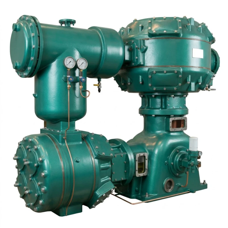
Special Air Compressor for Glass Bottle Making — Reciprocating Piston Series
Two-Series Glass Container Production Air Supply System · Forming Air 0.25–0.50 MPa, 10–300 m³/min · Oil-Free Mould Air 0.60–1.00 MPa, 3–150 m³/min · 45 to 2000 kW
The special air compressor for glass bottle making is a dedicated two-series compressed air system purpose-engineered for the specific air pressure and purity requirements of glass container forming lines, IS (individual section) machines, and glass blowing equipment. Unlike general industrial compressors that apply a single pressure standard to all uses, the glass bottle production process has two fundamentally different compressed air demands that must be met simultaneously and independently: a high-volume low-pressure forming air supply for IS machine forming sections, blank moulds, and blow heads; and a separate oil-free medium-pressure supply for mould cooling, instrument control valves, and precision pneumatic mechanisms that cannot tolerate any hydrocarbon contamination.
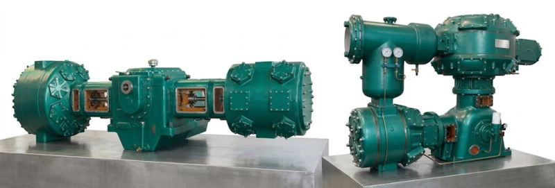
Series A — Glass Bottle Forming Air Compressor: 40 standard models covering flow outputs from 10 m³/min to 300 m³/min at discharge pressures of 0.25 to 0.50 MPa. Drive power ranges from 45 kW to 1,400 kW with voltage options of 380 V, 6 kV, and 10 kV. All models use twin-column single-stage or two-stage reciprocating piston configuration (3L, LW, 4L, L5.5, L8, DW, HW series), providing robust high-volume forming air supply matched to the typical operating pressure of IS machine forming sections. Custom single-unit capacity up to 2,000 kW available on request.
Series B — Oil-Free Air Compressor for Glass Moulds and Instrument Air: 15 standard models covering flow outputs from 3 m³/min to 150 m³/min at discharge pressures of 0.60 to 1.00 MPa. These models use PTFE piston rings and distance piece isolation to deliver compressed air with zero oil carry-over to mould cooling circuits, IS machine control air, and glass forming plant instrument air systems where oil contamination would cause mould surface staining, pneumatic valve failure, or product quality defects. Custom single-unit capacity up to 2,000 kW available on request.
Both series are proven in float glass plants, container glass factories, pharmaceutical glass tube drawing lines, and specialty glass forming facilities. All models are available with 380 V low-voltage supply for smaller installations and 6 kV or 10 kV medium-voltage motors for large glass plants with direct medium-voltage site distribution.
Forming Air: 10–300 m³/min
0.25–0.50 MPa Forming
Oil-Free: 3–150 m³/min
0.60–1.00 MPa Oil-Free
45–2000 kW
380 V / 6 kV / 10 kV
55 Standard Models
Typical applications: IS machine container glass production lines · Pharmaceutical glass vial and ampoule forming · Wine bottle and spirits container manufacturing · Food glass jar and preserve container lines · Perfume and cosmetic bottle forming · Float glass plant instrument air · Specialty glass tube drawing and shaping · Glass insulator and technical glass forming · Flat glass processing plant air utilities
Series A — Glass Bottle Forming Air Compressor
For IS Machine Forming Air Supply · Discharge Pressure 0.25–0.50 MPa · Flow 10–300 m³/min
Series A models supply the main forming air demand of IS machine glass bottle production lines — the high-volume, moderate-pressure compressed air used for blank mould pressing, blow head air, neck ring cooling, and section timing control. All 40 standard models use twin-column single-stage or twin-column two-stage reciprocating piston configurations. The number before the slash indicates flow in m³/min; the number after indicates pressure in bar (e.g. LW-10/3.5 = 10 m³/min at 0.35 MPa). Custom single-unit output up to 2,000 kW available on request.
| No. | Model | Pattern | Flow (m³/min) | Pressure (MPa) | Dimensions L×W×H (mm) | Weight (t) | Power (kW) | Voltage (V) |
|---|---|---|---|---|---|---|---|---|
| 1 | 3L-10/3.5 | Twin-col. single-stage | 10 | 0.35 | 1968×910×1820 | 1.60 | 45 | 380 |
| 2 | LW-10/3.5 | Twin-col. single-stage | 10 | 0.35 | 2048×910×2010 | 1.80 | 45 | 380 |
| 3 | 3L-10/4 | Twin-col. two-stage | 10 | 0.40 | 1968×910×2431 | 1.80 | 45 | 380 |
| 4 | LW-10/4 | Twin-col. two-stage | 10 | 0.40 | 2048×910×2070 | 1.80 | 45 | 380 |
| 5 | 3L-15/3.5 | Twin-col. single-stage | 15 | 0.35 | 1968×910×2431 | 1.70 | 75 | 380 |
| 6 | LW-15/3.5 | Twin-col. single-stage | 15 | 0.35 | 2048×910×2010 | 1.80 | 75 | 380 |
| 7 | 3L-20/3 | Twin-col. single-stage | 20 | 0.30 | 1968×910×2431 | 1.70 | 75 | 380 |
| 8 | LW-20/3 | Twin-col. single-stage | 20 | 0.30 | 2048×910×2070 | 1.80 | 75 | 380 |
| 9 | LW-22/2.5 | Twin-col. single-stage | 22 | 0.25 | 2048×910×2070 | 1.80 | 75 | 380 |
| 10 | 4L-20/4 | Twin-col. two-stage | 20 | 0.40 | 2260×1550×1935 | 2.50 | 90 | 380 |
| 11 | LW-20/4 | Twin-col. two-stage | 20 | 0.40 | 2630×1550×2332 | 3.00 | 90 | 380 |
| 12 | LW-25/3.5 | Twin-col. single-stage | 25 | 0.35 | 2685×1550×2120 | 3.00 | 110 | 380 |
| 13 | 4L-30/4 | Twin-col. two-stage | 30 | 0.40 | 2260×1550×1935 | 3.00 | 132 | 380 |
| 14 | LW-30/4 | Twin-col. two-stage | 30 | 0.40 | 2975×1550×2370 | 3.40 | 132 | 380 |
| 15 | 4L-40/2~3.2 | Twin-col. single-stage | 40 | 0.20 to 0.32 | 2620×1550×2380 | 3.00 | 132 | 380 |
| 16 | LW-40/3.2 | Twin-col. single-stage | 40 | 0.32 | 2926×1550×2690 | 3.20 | 132 | 380 |
| 17 | 4L-40/4 | Twin-col. two-stage | 40 | 0.40 | 2670×1550×2065 | 3.00 | 160 | 380 |
| 18 | LW-40/4 | Twin-col. two-stage | 40 | 0.40 | 2975×1550×2370 | 3.40 | 160 | 380 |
| 19 | L5.5-50/4 | Twin-col. two-stage | 50 | 0.40 | 2910×1600×1920 | 4.40 | 200 | 380 |
| 20 | LW-50/4 | Twin-col. two-stage | 50 | 0.40 | 2995×1600×2170 | 4.82 | 200 | 380 |
| 21 | L5.5-55/4.5 | Twin-col. two-stage | 55 | 0.45 | 2910×1600×1920 | 4.40 | 240 (250) | 380/6K or 10K |
| 22 | LW-55/4.5 | Twin-col. two-stage | 55 | 0.45 | 2995×1600×2170 | 4.82 | 240 (250) | 380/6K or 10K |
| 23 | L5.5-60/4 | Twin-col. two-stage | 60 | 0.40 | 2910×1600×1920 | 4.40 | 240 (250) | 380/6K or 10K |
| 24 | LW-60/4 | Twin-col. two-stage | 60 | 0.40 | 2995×1600×2170 | 4.82 | 240 (250) | 380/6K or 10K |
| 25 | L5.5-70/3.5 | Twin-col. two-stage | 70 | 0.35 | 2555×1120×2276 | 4.80 | 260 | 380/6K or 10K |
| 26 | LW-70/3.5 | Twin-col. two-stage | 70 | 0.35 | 2188×1600×2195 | 5.24 | 260 | 380/6K or 10K |
| 27 | LW-80/2.5 | Twin-col. single-stage | 80 | 0.25 | 2912×1600×2196 | 4.70 | 280 | 380/6K or 10K |
| 28 | LW-80/3.5 | Twin-col. two-stage | 80 | 0.35 | 2620×1600×2620 | 6.65 | 355 | 380/6K or 10K |
| 29 | DW-90/4 | Twin-col. two-stage | 90 | 0.40 | 5500×3518×2535 | 13.00 | 400 | 6K or 10K |
| 30 | DW-100/3.5 | Twin-col. two-stage | 100 | 0.35 | 5500×3353×2535 | 13.00 | 480 | 6K or 10K |
| 31 | DW-110/4 | Twin-col. two-stage | 110 | 0.40 | 5500×3518×2535 | 13.50 | 500 | 6K or 10K |
| 32 | DW-115/3.5 | Twin-col. two-stage | 115 | 0.35 | 5500×3518×2535 | 13.50 | 480 | 6K or 10K |
| 33 | DW-120/4 | Twin-col. two-stage | 120 | 0.40 | 5500×3518×2535 | 13.50 | 550 | 6K or 10K |
| 34 | DW-125/4 | Twin-col. two-stage | 125 | 0.40 | 5500×3518×2535 | 13.50 | 550 | 6K or 10K |
| 35 | DW-130/4 | Twin-col. two-stage | 130 | 0.40 | 5370×3540×2660 | 14.00 | 600 | 6K or 10K |
| 36 | DW-150/4 | Twin-col. two-stage | 150 | 0.40 | 6000×3640×3000 | 19.00 | 710 | 6K or 10K |
| 37 | DW-190/2.7 | Twin-col. single-stage | 190 | 0.27 | 5456×3518×1710 | 13.00 | 630 | 6K or 10K |
| 38 | HW-200/4 | Four-col. two-stage | 200 | 0.40 | 5456×6000×2535 | 26.00 | 850 | 6K or 10K |
| 39 | HW-240/4.5 | Four-col. two-stage | 240 | 0.45 | 5456×6400×2800 | 26.00 | 1100 | 6K or 10K |
| 40 | HW-300/4 | Four-col. two-stage | 300 | 0.40 | 6000×8500×3000 | 40.00 | 1400 | 6K or 10K |
Note: Custom single-unit capacity within the 11 kW to 2,000 kW range is available on request for Series A forming air compressors. Dimensions are approximate (host assembly only). Weight listed is main host only. Contact our technical team for foundation drawings and full installation specifications.
Series B — Oil-Free Air Compressor for Glass Moulds and Instrument Air
For Mould Cooling, IS Machine Control Air, and Instrument Air · Discharge Pressure 0.60–1.00 MPa · Flow 3–150 m³/min
Series B models supply the oil-free medium-pressure air required for IS machine pneumatic control systems, mould cooling air, and glass plant instrument air. All 15 standard models use twin-column two-stage reciprocating piston configuration with PTFE piston rings, rod packing, and distance piece isolation to guarantee zero oil carry-over into the compressed air stream. Oil contamination in IS machine control air or mould cooling circuits causes mould surface deposits, pneumatic valve sticking, and product contamination in food and pharmaceutical glass. Custom single-unit capacity up to 2,000 kW available on request. Note: this series is also suitable for glass container factories requiring lubricated (oil-containing) compressed air at 0.60 to 1.00 MPa — available with standard cast-iron piston rings on request.
| No. | Model | Pattern | Flow (m³/min) | Pressure (MPa) | Dimensions L×W×H (mm) | Weight (t) | Power (kW) | Voltage (V) |
|---|---|---|---|---|---|---|---|---|
| 1 | ZW-3/7 | Twin-col. two-stage | 3 | 0.70 | 720×763×1274 | 0.58 | 22 | 380 |
| 2 | ZW-6/8 | Twin-col. two-stage | 6 | 0.80 | 2250×1296×2350 | 2.00 | 45 | 380 |
| 3 | LW-10/8 | Twin-col. two-stage | 10 | 0.80 | 2340×910×2070 | 1.80 | 65 | 380 |
| 4 | LW-20/8 | Twin-col. two-stage | 20 | 0.80 | 2632×1550×2330 | 3.00 | 132 | 380 |
| 5 | LW-30/8 | Twin-col. two-stage | 30 | 0.80 | 2890×1600×2173 | 4.12 | 200 | 380 |
| 6 | LW-40/8 | Twin-col. two-stage | 40 | 0.80 | 2890×1600×2190 | 4.12 | 240 (250) | 380/6K or 10K |
| 7 | LW-50/8 | Twin-col. two-stage | 50 | 0.80 | 2380×1685×2235 | 6.50 | 350 | 380/6K or 10K |
| 8 | LW-60/8 | Twin-col. two-stage | 60 | 0.80 | 2380×1500×2560 | 6.50 | 350 | 380/6K or 10K |
| 9 | DW-75/8 | Twin-col. two-stage | 75 | 0.80 | 5456×3518×2535 | 13.00 | 450 | 6K or 10K |
| 10 | DW-85/8 | Twin-col. two-stage | 85 | 0.80 | 5456×3518×2535 | 13.00 | 500 | 6K or 10K |
| 11 | DW-90/8 | Twin-col. two-stage | 90 | 0.80 | 5440×3518×2620 | 13.00 | 550 | 6K or 10K |
| 12 | DW-100/8 | Twin-col. two-stage | 100 | 0.80 | 5456×3518×2535 | 13.00 | 600 | 6K or 10K |
| 13 | DW-110/8 | Twin-col. two-stage | 110 | 0.80 | 5500×3518×2535 | 13.00 | 630 | 6K or 10K |
| 14 | DW-130/8 | Twin-col. two-stage | 130 | 0.80 | 6000×3640×3000 | 18.00 | 800 | 6K or 10K |
| 15 | DW-150/8 | Twin-col. two-stage | 150 | 0.80 | 6000×3640×3000 | 19.00 | 900 | 6K or 10K |
Note: Custom single-unit capacity within the 22 kW to 2,000 kW range is available on request for Series B oil-free and oil-containing variants. Lubricated (oil-containing) versions at 0.60 to 1.00 MPa are available using standard cast-iron piston rings on the same frame for applications where oil-free status is not required.
Why Glass Bottle Making Needs Two Separate Compressed Air Systems
The IS Machine Forming Process and Its Air Demand
The IS (Individual Section) machine is the global standard for high-speed glass container production. Each section of the IS machine independently forms glass gobs into finished containers through a sequence of blank mould pressing or blowing, invert, blow-and-blow or press-and-blow forming, and take-out operations — all timed by compressed air acting on pneumatic cylinders, rotary mechanisms, and blow heads. A modern IS machine running 12 to 16 sections at high speed has a very large and rapidly cycling compressed air demand, with hundreds of pneumatic events per minute across all sections. This demand is met by Series A — the forming air compressor, supplying high-volume air at 0.25 to 0.50 MPa from the station header through a distribution ring main to each IS machine section.
Why Mould and Instrument Air Must Be Oil-Free
Alongside the IS machine forming air, the glass plant needs a separate medium-pressure air supply at 0.60 to 1.00 MPa for mould cooling air jets, neck ring cooling, IS machine electronic timing valve pilots, and plant instrument control valves. This air supply has two critical purity requirements. First, mould cooling air contacts the hot glass surface directly through cooling jets and must carry no oil — oil deposits on mould surfaces cause glass surface defects, black spots on the container sidewall, and failed container inspections. Second, electronic pilot valves and timing solenoids in modern IS machine control systems have very small orifices that clog rapidly with oil vapour condensate, causing valve stiction, timing drift, and production stoppages. Series B — the oil-free compressor meets both requirements with intrinsically oil-free air from PTFE piston rings and distance piece isolation.
Glass Bottle Making vs Plastic Bottle Blowing — Air Supply Comparison
It is worth noting that glass container forming and plastic container blowing have fundamentally different air pressure requirements. Glass IS machines operate at relatively low forming air pressures of 0.25 to 0.50 MPa because glass is a viscous fluid at forming temperature that responds to low differential pressures. In contrast, plastic preform blowing — such as the PET bottle stretch-blow moulding process used in modern high-output blow moulding machines — requires high blowing air pressure of 30 to 40 bar (3.0 to 4.0 MPa) because the semi-solid PET preform must be rapidly and fully stretched against the mould wall under high pressure. This fundamental difference in operating pressure means that the glass bottle forming air compressor series described on this page is not suitable for PET plastic bottle production, which requires a completely different high-pressure compressor technology. Conversely, a plastic bottle blow moulding machine compressor cannot be adapted for glass IS machine forming air duty.
Two-Stage Compression at 0.30 to 0.50 MPa
At the forming air pressure range of 0.30 to 0.50 MPa, two-stage compression provides meaningfully better efficiency than single-stage designs, reducing inter-stage discharge temperature and improving volumetric efficiency. Single-stage models are available at the lower end of the pressure range (0.25 to 0.35 MPa) where the compression ratio is modest enough that the thermodynamic advantage of two-stage compression is smaller. Series B oil-free models at 0.60 to 1.00 MPa all use two-stage compression, which is essential at these higher pressure ratios to maintain acceptable PTFE ring operating temperature and achieve rated volumetric efficiency.
6 Core Advantages of This Glass Bottle Making Compressor System
Purpose-Matched Pressure for IS Machine Forming
Series A models are pressure-rated specifically at 0.25 to 0.50 MPa — the actual operating range of IS machine glass forming sections — rather than the 0.70 to 1.00 MPa typical of general industrial compressors. This means cylinder bore, valve timing, and motor selection are matched to the real forming air pressure requirement, achieving better specific energy consumption at forming pressures than a general industrial compressor throttled back from high-pressure duty.
Intrinsically Oil-Free Series B for Mould Air
Series B uses PTFE piston rings and distance piece isolation to deliver genuinely oil-free compressed air to mould cooling and instrument air circuits — not oil-reduced air dependent on downstream coalescing filters. If a downstream filter element were to fail in an oil-injected screw compressor system, oil would reach the mould surfaces and timing valves immediately. Series B eliminates this risk entirely because there is no oil source in the compression cylinder to begin with.
Comprehensive Flow Range — 10 to 300 m³/min Forming Air
With 40 Series A models covering 10 to 300 m³/min at forming pressures, this series covers glass plants from single IS machine lines (10 to 30 m³/min) through to large multi-machine container glass factories (150 to 300 m³/min). The four-column HW-200/4, HW-240/4.5, and HW-300/4 flagship models serve the largest glass container production facilities with a single high-output unit rather than multiple smaller units, reducing compressor room footprint and maintenance staffing requirements.
Medium-Voltage Motors for Large Glass Plants
Large container glass factories typically operate medium-voltage site distribution at 6 kV or 10 kV. Both Series A and Series B offer 6 kV and 10 kV motor options from 240 kW upward, enabling direct connection to medium-voltage plant substations without step-down transformer cost or distribution energy losses. This simplifies electrical installation in new glass plant construction and reduces the total installed cost of the compressed air station for large glass producers.
Field-Serviceable During Planned Production Shutdowns
IS machine glass plants operate on planned production cycle patterns with regular furnace repairs and IS machine rebuilds. Reciprocating compressor maintenance intervals — valve plates every 2,000 to 4,000 hours, piston rings every 4,000 to 8,000 hours — align naturally with planned glass plant maintenance windows. Valve and ring maintenance is performed by plant maintenance staff with standard tools during planned outages, without requiring specialist service teams or extended compressor room shutdowns that would delay production restart.
Proven Four-Decade Track Record in Glass Industry
This reciprocating piston compressor series has been the standard compressed air technology for glass container plants in China and across export markets for over four decades. Reference installations include wine bottle plants running 12-section IS machines, pharmaceutical glass vial forming lines, spirits bottle factories with multiple forming machines, and large-scale food glass jar production facilities. The robust cast-iron cylinder and forged crankshaft construction is proven to withstand the demanding continuous-duty environment of 24-hour glass plant production operations.
Typical Application Scenarios
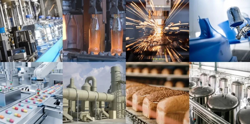
Container Glass IS Machine Lines
Standard IS machine container glass production — wine bottles, spirits bottles, beer bottles, soft drink bottles, food jars, and preserve containers — is the primary application for this two-series compressor system. A typical single 8-section IS machine requires approximately 25 to 45 m³/min of forming air at 0.35 to 0.45 MPa and 8 to 15 m³/min of oil-free control air at 0.70 to 0.80 MPa. A glass plant running four IS machines in parallel would require Series A capacity of 100 to 180 m³/min and Series B capacity of 30 to 60 m³/min from the station header.
Series A: LW-30/4 to DW-150/4 | Series B: LW-30/8 to LW-60/8
Pharmaceutical Glass Vials and Ampoules
Pharmaceutical glass vial and ampoule forming lines use IS machines or rotary forming machines operating at lower speeds but with extremely high air purity requirements because the glass containers will ultimately hold injectable drugs. Oil contamination of forming air or mould cooling air in pharmaceutical glass production is a GMP (Good Manufacturing Practice) violation that can result in batch rejection or facility shutdown. Series B oil-free models are mandatory in pharmaceutical glass forming lines; Series A models for pharmaceutical forming air must also meet validated oil-free standards or use oil-free configuration.
Series A: LW-10/3.5 to LW-40/4 | Series B: ZW-3/7 to LW-20/8
Large Container Glass Factories
Large container glass factories with 8 to 16 IS machines running simultaneously require total forming air supplies of 200 to 300 m³/min or more. The HW-200/4, HW-240/4.5, and HW-300/4 four-column models serve these large facilities with a single compressor unit per forming air supply station, simplifying station design and reducing the number of maintenance items and spare parts holdings compared with multiple smaller units. The 6 kV and 10 kV motor options on these large models match the medium-voltage site electrical systems typical of modern large glass factories.
Series A: HW-200/4 to HW-300/4 | Series B: DW-75/8 to DW-150/8
Perfume, Cosmetic, and Specialty Glass
Perfume and cosmetic glass bottle forming requires high precision and very low defect rates because the containers represent premium brand packaging. Oil contamination of mould air in perfume glass forming causes permanent surface staining on the polished mould surface, resulting in visible blemishes on high-value containers that must be rejected. Series B oil-free instrument and mould air is essential in perfume glass production; Series A forming air supply at 0.35 to 0.45 MPa for press-and-blow or blow-and-blow IS machine forming of small specialty containers typically requires 10 to 30 m³/min from a smaller LW-series forming air unit.
Series A: 3L-10/3.5 to LW-40/4 | Series B: ZW-3/7 to LW-20/8
Float Glass and Flat Glass Plant Instrument Air
Float glass production lines and flat glass processing plants require instrument air for control valve actuation, glass conveyor positioning pneumatics, and cutting station actuators at 0.60 to 0.80 MPa. While float glass does not use IS machine blow-and-blow forming, the plant instrument air system requires clean, dry, oil-free compressed air for the same reason as any process plant instrument air supply — to prevent control valve failures, positioner fouling, and instrument damage. Series B oil-free models supply float glass plant instrument air needs from 3 m³/min for small processing operations to 60 m³/min for large float glass lines.
Series B: ZW-3/7 to LW-60/8
Glass Insulator and Technical Glass Forming
Glass insulator production for electrical transmission lines and substations uses press forming processes that require compressed air at 0.30 to 0.45 MPa for press actuators, transfer mechanisms, and cooling air. Technical glass forming for laboratory glassware, sight glasses, and specialty optical glass uses a range of press and blow forming processes. The mid-range LW and L5.5 series (20 to 60 m³/min at 0.35 to 0.45 MPa) covers the typical forming air demand of glass insulator production lines and technical glass forming operations, with single-stage models available for the lower end of this pressure range.
Series A: LW-20/3 to L5.5-60/4 | Series B: LW-10/8 to LW-40/8
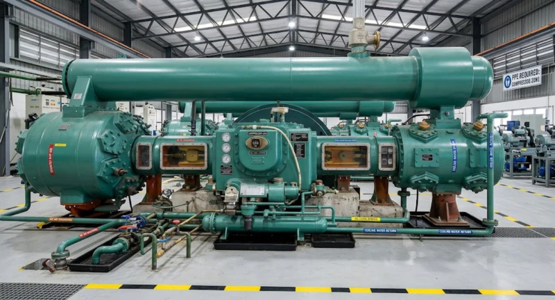
Installed at Customer Sites
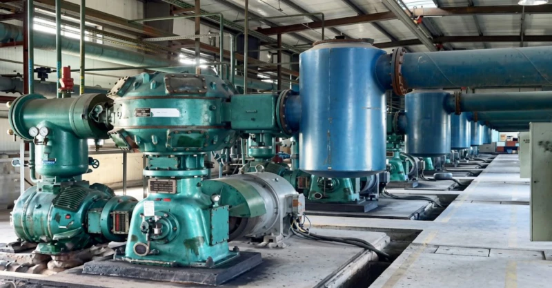
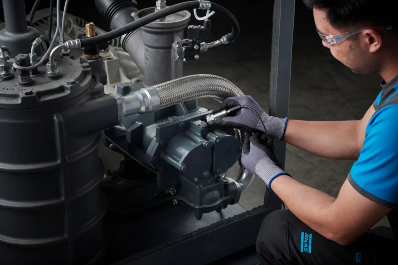
This two-series compressor system has been installed in forming air stations and instrument air stations across container glass plants, pharmaceutical glass vial facilities, and specialty glass factories. The following images show representative field installations and in-progress maintenance operations demonstrating the compressor room layout, parallel multi-unit arrangements, and field service procedures at customer sites.
How to Size a Two-Series Glass Bottle Making Compressor Station
Determine IS Machine Count and Section Configuration
The starting point for sizing the forming air station is the number of IS machines and their section count. A typical 8-section IS machine running at high speed requires 30 to 45 m³/min of forming air at 0.35 to 0.45 MPa. A 10-section machine requires approximately 40 to 55 m³/min. Add 15 to 20% spare capacity for expansion and air receiver top-up. For plants with multiple IS machines, sum the individual machine demands and size the forming air station for the total simultaneous demand plus spare capacity. The IS machine manufacturer can provide the specific air consumption data for their machine model and speed in their technical documentation.
Set the Forming Air Pressure — Series A
IS machine manufacturers specify a required forming air pressure at the machine inlet, typically in the range 0.30 to 0.45 MPa. Add 0.03 to 0.07 MPa for distribution ring main loss between the compressor station and the most distant IS machine. The compressor discharge pressure should be the machine inlet pressure requirement plus distribution loss, rounded up to the nearest standard model pressure rating. Most IS machine forming lines operate best with a 0.40 MPa compressor discharge pressure providing adequate distribution pressure at the machine inlet. Higher-speed machines and deeper-cavity container moulds may require 0.45 to 0.50 MPa.
Size the Oil-Free Instrument Air Station — Series B
The oil-free instrument air demand is typically 20 to 30% of the forming air demand in volume terms. It must be supplied at 0.60 to 0.80 MPa to operate IS machine electronic timing valves, section control pilots, and mould cooling air jets. Calculate the total instrument air demand from the IS machine technical data for pilot air and cooling air separately, and size the Series B compressor station for this demand plus 20% spare capacity. The Series B and Series A stations are fully independent systems with separate headers, air receivers, after-coolers, and distribution networks — they must not be cross-connected as this would compromise the oil-free integrity of the instrument air supply.
Plan for Redundancy and Phased Expansion
IS machine glass plants are continuous 24-hour operations where a compressor station failure causes immediate production loss on all running IS machines simultaneously. Minimum recommended station design is N plus 1 redundancy — at least one spare compressor unit that can be started manually or automatically on demand. For large plants, N plus 2 redundancy with automatic lead-lag sequencing provides maximum uptime assurance. Both Series A and Series B stations should be designed with expansion capacity — spare space for additional compressor units and appropriate manifold sizing — to accommodate planned IS machine line additions without rebuilding the compressed air infrastructure.
Air Treatment and Distribution Design
Series A forming air stations require: properly sized air receiver (minimum 10 times compressor FAD in litres), after-cooler to reduce discharge temperature, and automatic drain traps on the receiver and distribution low points to remove condensate. Formed glass surfaces can tolerate moisture in the forming air without significant quality impact, so refrigerated drying is not usually required on Series A. Series B oil-free instrument air stations additionally require a refrigerated compressed air dryer (pressure dew point plus 3 deg C) and coalescing particulate filter to deliver dry, clean oil-free instrument air to the IS machine timing valve panel. Both station distribution systems should be ring mains rather than dead-end branches to equalise pressure across all IS machine connection points.
Frequently Asked Questions — Glass Bottle Making Air Compressor
Ready to Specify a Compressed Air System for Your Glass Bottle Plant?
Our engineering team provides free forming air and instrument air station sizing for glass container production projects — including IS machine demand calculation, two-series station design, foundation load data, electrical starting specifications, and spare parts holding recommendations. Factory-direct pricing, global export, and full project technical documentation for Series A and Series B compressor packages.