
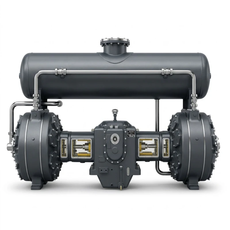
Oil-Free Air Compressor for Fermentation — Two-Stage Reciprocating Series
Oil-Free Piston Compressor for Clean Air Supply in Fermentation, Bioreactors, and Industrial Bioprocessing · 0.10 to 0.50 MPa · 2 to 600 m³/min · 13 to 2000 kW
The oil-free air compressor for fermentation is a two-stage piston-type compressed air machine purpose-engineered to supply clean, hydrocarbon-free compressed air for fermentation tanks, bioreactors, yeast cultivation systems, and industrial bioprocessing utilities. Available in 50 standard models spanning flow outputs from 2 m³/min to 600 m³/min at discharge pressures of 0.10 to 0.50 MPa, this series provides the complete range from small laboratory fermentation installations to large-scale pharmaceutical and food-grade bioprocessing plants. Drive power ranges from 13 kW to 2,000 kW, with voltage options of 380 V, 6 kV, and 10 kV to suit every grid connection requirement.
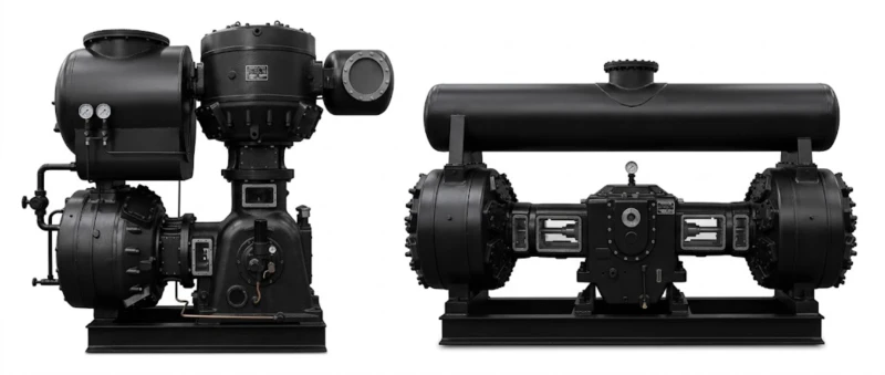
All models in this series use a twin-column two-stage reciprocating compression configuration (LW-type or DW-type cylinder arrangement) delivering efficient compression at low discharge pressures with zero oil contamination. The design uses PTFE-filled piston rings and rod packing in place of conventional lubricated cast-iron rings, completely eliminating lubricating oil contact with the compression cylinder and ensuring that compressed air delivered to fermentation and bioprocessing circuits is free from hydrocarbon contamination. The series also covers single-stage models (LW single-stage) for very low pressure fermentation aeration at 0.15 to 0.25 MPa and two-stage models for pressures up to 0.50 MPa. Custom models up to 2,000 kW are available on request across the full range.
Designed for continuous duty in hygienic industrial service, the series incorporates robust cast-iron cylinder construction, precision-machined crankshafts, PTFE piston rings verified for oil-zero operation, integrated inter-stage cooling, and distance piece isolation between crankcase and compression cylinder to prevent any possibility of oil migration. Proven in pharmaceutical fermentation, food and beverage bioprocessing, industrial enzyme production, and water treatment aeration worldwide.
2 to 600 m³/min
0.10 to 0.50 MPa
13 to 2000 kW
380 V / 6 kV / 10 kV
50 Standard Models
PTFE Piston Rings
Distance Piece Isolation
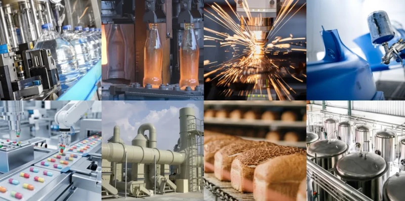
Typical applications: Pharmaceutical fermentation and bioreactor aeration · Food and beverage yeast cultivation · Industrial enzyme and amino acid production · Antibiotics and fine chemical bioprocessing · Activated sludge aeration for water treatment · Aquaculture oxygenation · Hospital medical air supply · Textile and paper mill process air · Laboratory pilot plant compressed air
Technical Parameters — Full Model Range (50 Models)
Model designation key: The number before the slash indicates flow output in m³/min; the number after the slash indicates working pressure in bar (e.g. LW-10/4 = L-type W-arrangement, 10 m³/min at 0.40 MPa). Prefix letters indicate cylinder arrangement and stage type: ZW = Z-type W-arrangement two-stage, LW = L-type W-arrangement (single-stage or two-stage), DW = D-type W-arrangement two-stage, HW = H-type four-column two-stage. All models are oil-free piston type with PTFE piston rings. The “Pattern” column lists single-stage or two-stage configuration as used in factory documentation.
| No. | Model | Pattern | Flow (m³/min) | Pressure (MPa) | Dimensions L×W×H (mm) | Weight (t) | Power (kW) | Voltage (V) |
|---|---|---|---|---|---|---|---|---|
| 1 | ZW-2/4 | Twin-col. two-stage | 2 | 0.40 | 763×720×1274 | 0.40 | 13 | 380 |
| 2 | ZW-4.5/3 | Twin-col. two-stage | 4.5 | 0.30 | 763×720×1274 | 0.40 | 22 | 380 |
| 3 | ZW-6/4 | Twin-col. two-stage | 6 | 0.40 | 2250×1296×2200 | 2.00 | 37 | 380 |
| 4 | LW-10/3 | Twin-col. single-stage | 10 | 0.30 | 2048×910×2070 | 1.80 | 45 | 380 |
| 5 | LW-10/4 | Twin-col. two-stage | 10 | 0.40 | 2048×910×2070 | 1.80 | 45 | 380 |
| 6 | LW-15/3.5 | Twin-col. single-stage | 15 | 0.35 | 2048×910×2010 | 1.80 | 75 | 380 |
| 7 | LW-20/3 | Twin-col. two-stage | 20 | 0.30 | 2048×910×2070 | 1.80 | 75 | 380 |
| 8 | LW-20/4 | Twin-col. two-stage | 20 | 0.40 | 2630×1550×2332 | 3.00 | 90 | 380 |
| 9 | LW-22/2.5 | Twin-col. single-stage | 22 | 0.25 | 2048×910×2070 | 1.80 | 75 | 380 |
| 10 | LW-25/4 | Twin-col. two-stage | 25 | 0.40 | 2975×1550×2370 | 3.40 | 110 | 380 |
| 11 | LW-30/3.5 | Twin-col. single-stage | 30 | 0.35 | 2926×1550×2690 | 3.20 | 132 | 380 |
| 12 | LW-30/4 | Twin-col. two-stage | 30 | 0.40 | 2975×1550×2370 | 3.40 | 132 | 380 |
| 13 | LW-35/2.5 | Twin-col. single-stage | 35 | 0.25 | 3136×1550×2900 | 3.40 | 132 | 380 |
| 14 | LW-40/2~3.2 | Twin-col. single-stage | 40 | 0.20 to 0.32 | 2580×1550×1935 | 3.00 | 132 | 380 |
| 15 | LW-40/4 | Twin-col. two-stage | 40 | 0.40 | 2975×1550×2370 | 3.40 | 160 | 380 |
| 16 | LW-44/2 | Twin-col. single-stage | 44 | 0.20 | 2926×1550×2690 | 3.20 | 132 | 380 |
| 17 | LW-50/2 | Twin-col. single-stage | 50 | 0.20 | 2926×1550×2690 | 3.20 | 160 | 380 |
| 18 | LW-55/4.5 | Twin-col. two-stage | 55 | 0.45 | 2910×1600×1920 | 4.40 | 240 (250) | 380/6K/10K |
| 19 | LW-60/1.5 | Twin-col. single-stage | 60 | 0.15 | 2350×1550×2325 | 3.50 | 160 | 380 |
| 20 | LW-60/4 | Twin-col. two-stage | 60 | 0.40 | 2995×1600×2170 | 4.82 | 240 (250) | 380/6K/10K |
| 21 | LW-70/3 | Twin-col. two-stage | 70 | 0.30 | 2188×1600×2195 | 5.24 | 240 (250) | 380/6K/10K |
| 22 | LW-70/3.5 | Twin-col. two-stage | 70 | 0.35 | 2188×1600×2195 | 5.24 | 260 | 380/6K/10K |
| 23 | LW-70/5 | Twin-col. two-stage | 70 | 0.50 | 2555×1120×2276 | 4.80 | 315 | 380/6K/10K |
| 24 | LW-80/2.2 | Twin-col. single-stage | 80 | 0.22 | 2600×2870×1920 | 3.70 | 240 (250) | 380/6K/10K |
| 25 | LW-80/2.5 | Twin-col. single-stage | 80 | 0.25 | 2912×1600×2196 | 4.70 | 280 | 380/6K/10K |
| 26 | LW-80/3.5 | Twin-col. two-stage | 80 | 0.35 | 2620×1600×2620 | 6.65 | 355 | 380/6K/10K |
| 27 | LW-90/2.5 | Twin-col. single-stage | 90 | 0.25 | 2620×1600×2620 | 7.00 | 355 | 380/6K/10K |
| 28 | LW-100/1.5 | Twin-col. single-stage | 100 | 0.15 | 2910×1600×1920 | 4.82 | 260 | 380/6K/10K |
| 29 | LW-110/1.5 | Twin-col. single-stage | 110 | 0.15 | 2600×2870×1920 | 4.82 | 280 | 380/6K/10K |
| 30 | LW-113/2 | Twin-col. single-stage | 113 | 0.20 | 2750×1500×2820 | 6.00 | 350 | 380/6K/10K |
| 31 | LW-116/1.5 | Twin-col. single-stage | 116 | 0.15 | 2750×1500×2820 | 6.00 | 280 | 380/6K/10K |
| 32 | DW-90/4 | Twin-col. two-stage | 90 | 0.40 | 5500×3518×2535 | 13.00 | 400 | 6K/10K |
| 33 | DW-100/2.5 | Twin-col. single-stage | 100 | 0.25 | 5000×1600×2450 | 6.00 | 350 | 6K/10K |
| 34 | DW-100/3.5 | Twin-col. two-stage | 100 | 0.35 | 5500×3353×2535 | 13.00 | 480 | 6K/10K |
| 35 | DW-115/3.5 | Twin-col. two-stage | 115 | 0.35 | 5500×3518×2535 | 13.00 | 480 | 6K/10K |
| 36 | DW-120/3.2 | Twin-col. two-stage | 120 | 0.32 | 5500×3518×2535 | 13.00 | 480 | 6K/10K |
| 37 | DW-120/4 | Twin-col. two-stage | 120 | 0.40 | 5500×3518×2535 | 13.00 | 550 | 6K/10K |
| 38 | DW-125/4 | Twin-col. two-stage | 125 | 0.40 | 5500×3518×2535 | 13.00 | 550 | 6K/10K |
| 39 | DW-150/2.7 | Twin-col. single-stage | 150 | 0.27 | 5500×3518×2535 | 13.00 | 550 | 6K/10K |
| 40 | DW-150/4 | Twin-col. two-stage | 150 | 0.40 | 6000×3640×3000 | 19.00 | 650 | 6K/10K |
| 41 | DW-190/2.2 | Twin-col. single-stage | 190 | 0.22 | 5456×3518×1710 | 13.00 | 600 | 6K/10K |
| 42 | DW-190/2.7 | Twin-col. single-stage | 190 | 0.27 | 5456×3518×1710 | 13.00 | 630 | 6K/10K |
| 43 | DW-200/2.2 | Twin-col. single-stage | 200 | 0.22 | 5456×3518×1710 | 13.00 | 630 | 6K/10K |
| 44 | DW-300/1 | Twin-col. single-stage | 300 | 0.10 | 6200×3640×2860 | 14.00 | 550 | 6K/10K |
| 45 | DW-300/2.2 | Twin-col. single-stage | 300 | 0.22 | 6200×3640×2860 | 15.00 | 950 | 6K/10K |
| 46 | HW-200/4 | Four-col. two-stage | 200 | 0.40 | 5456×6000×2535 | 26.00 | 850 | 6K/10K |
| 47 | HW-300/4 | Four-col. two-stage | 300 | 0.40 | 5456×6000×2535 | 26.00 | 1000 | 6K/10K |
| 48 | HW-380/2.5 | Four-col. single-stage | 380 | 0.25 | 5456×6000×2535 | 26.00 | 1260 | 6K/10K |
| 49 | HW-400/2.2 | Four-col. single-stage | 400 | 0.22 | 5456×6000×2535 | 26.00 | 1300 | 6K/10K |
| 50 | HW-600/2.2 | Four-col. single-stage | 600 | 0.22 | 5456×6000×2535 | 27.00 | 2000 | 6K/10K |
Note: Custom models within the 11 kW to 2,000 kW power range are available on request to cover non-standard flow and pressure requirements. Dimensions are approximate (host assembly only, excluding foundation and auxiliary piping). Weight listed is main host only. Voltage options of 380 V, 6 kV, and 10 kV depend on model size. Contact our technical team for foundation drawings and full installation specifications.
How It Works: Oil-Free Reciprocating Compression for Fermentation Air Supply
Oil-Free Compression Principle — PTFE Piston Rings and Distance Piece Isolation
Conventional lubricated reciprocating compressors use oil-wetted cast-iron piston rings that form a sealing film between piston and cylinder bore, resulting in small but measurable oil carry-over into the compressed air stream. In fermentation and bioprocessing applications, any hydrocarbon contamination of the aeration air entering the bioreactor inhibits microbial metabolism, contaminates the fermentation product, and may compromise sterility validation. The oil-free reciprocating compressor eliminates this risk by replacing cast-iron piston rings with self-lubricating PTFE composite rings (typically PTFE filled with glass fibre, bronze, or carbon) that provide sealing and reduce friction against the cylinder bore without any oil at all. Rod packing on the piston rod is similarly replaced with PTFE-based segmented rings. The result is an intrinsically oil-free air stream from the compression cylinder without any downstream filtration or absorption treatment required to achieve oil-free status.
A distance piece — an open vented chamber — is installed between the crankcase and the compression cylinder. This ensures that any oil vapour present in the crankcase atmosphere cannot migrate past the rod packing into the compression space. The distance piece is vented to atmosphere, so any leakage past the lower packing seal is released safely to air rather than entering the compressed air circuit. This double-barrier design provides a physical guarantee of oil-free compression independent of piston ring condition.
Single-Stage vs Two-Stage Configuration at Low Fermentation Pressures
Fermentation and bioreactor aeration typically requires compressed air at relatively low pressures of 0.10 to 0.35 MPa to overcome the hydrostatic head of the fermentation medium plus the pressure loss across sparger diffusers and control valves. At these pressure ratios (approximately 1.5:1 to 4:1), a single-stage configuration is often the most energy-efficient choice, avoiding the additional friction and heat of a second compression stage where the thermodynamic benefit of inter-stage cooling is modest. The series includes single-stage LW and DW models specifically configured for 0.15 to 0.30 MPa fermentation aeration. For higher pressure requirements at 0.35 to 0.50 MPa — such as deep tank bioreactors, high-viscosity fermentation media, or downstream air distribution systems with significant pressure reduction — two-stage models in the LW, DW, and HW series provide better specific energy consumption at these higher pressure ratios.
Cylinder Cooling and Discharge Temperature Management
Oil-free piston rings have higher friction than lubricated rings and generate more heat in the compression cylinder, which must be managed by adequate cylinder cooling. All models in this series use water-jacket cooling on cylinder bodies (closed-circuit cooling water at 30 to 40 deg C inlet temperature) and an inter-stage air-cooler between LP and HP stages on two-stage models. Discharge air temperature from the final stage is maintained below 160 deg C at rated conditions, protecting PTFE ring integrity over the full ring service life. Cooling water flow requirements and inlet temperature specifications are provided for each model in the installation manual.
6 Core Advantages of This Oil-Free Fermentation Air Compressor Series
Intrinsically Oil-Free — No Downstream Filtration Required
PTFE composite piston rings and packing combined with distance piece isolation deliver compressed air with zero oil content by design, not by downstream treatment. Unlike oil-injected screw compressors that rely on coalescing filters and activated-carbon adsorbers to achieve oil-free status, this reciprocating oil-free design cannot produce oil-contaminated air even if a downstream filter element fails. This intrinsic protection is the highest reliability standard for fermentation air supply in pharmaceutical and food-grade bioprocessing.
Widest Flow Range — 2 to 600 m³/min
With 50 standard models covering 2 m³/min to 600 m³/min from a single product family, this series provides oil-free fermentation air supply solutions from small pilot-plant bioreactors through to the largest commercial fermentation facilities producing amino acids, antibiotics, or industrial enzymes. A unified spare parts catalogue and consistent technical platform simplifies multi-unit station management and long-term maintenance planning for growing production sites.
Optimised for Low-Pressure Fermentation Aeration
Fermentation requires air at 0.10 to 0.35 MPa in most applications — far below the 0.7 to 1.0 MPa of conventional industrial compressors. This series is factory-configured at these low discharge pressures with cylinder bore, valve timing, and motor selection matched to the pressure ratio actually required, achieving better specific energy consumption at fermentation aeration pressures than industrial compressors throttled back from high-pressure duty or operated on pressure bypass.
Medium-Voltage Options for Large Fermentation Facilities
Large pharmaceutical fermentation facilities and industrial amino acid or citric acid plants operate medium-voltage site distribution at 6 kV or 10 kV. Models from 240 kW and above in this series are available with 6 kV and 10 kV motor options, enabling direct connection to medium-voltage bus bars without step-down transformer capital cost or distribution losses. This is particularly beneficial for large-scale plants running multiple high-flow DW or HW series compressors in parallel.
Field-Serviceable — Low Total Cost of Ownership
PTFE piston rings, valve plates, valve springs, and rod packing are all field-replaceable consumable items that can be changed by plant maintenance staff with standard workshop tools during scheduled shutdowns. Unlike oil-free screw compressors that require rotor replacement or specialist service team overhaul at long but infrequent intervals, the reciprocating oil-free compressor has predictable, frequent, low-cost maintenance events that are easily planned around production schedules.
Proven Track Record in Pharmaceutical and Food-Grade Service
This reciprocating oil-free compressor series has been the standard technology for large-scale pharmaceutical fermentation air supply in China and export markets for over four decades. Reference installations include penicillin and cephalosporin fermentation plants, monosodium glutamate and lysine production facilities, citric acid fermentation stations, and industrial enzyme production plants with individual compressor station capacities from 50 m³/min to over 1,000 m³/min using multiple units in parallel.
Typical Application Scenarios
Pharmaceutical Fermentation — Antibiotics and APIs
Penicillin, cephalosporin, erythromycin, and other antibiotic fermentation processes require continuous oil-free aeration at 0.20 to 0.35 MPa to support aerobic microbial metabolism in large bioreactors of 50 m³ to 500 m³ working volume. Any oil contamination of the aeration air would inhibit the producing organism, compromise batch yield, and trigger product quality failures under GMP (Good Manufacturing Practice) protocols. The oil-free reciprocating compressor meets pharmaceutical aeration air purity requirements without reliance on downstream oil removal systems that are potential single points of failure.
Recommended: LW-30/3.5 to DW-150/4
Amino Acid and Organic Acid Fermentation
Industrial amino acid production (lysine, glutamic acid, threonine) and organic acid fermentation (citric acid, lactic acid) operate at very large scale with individual fermenters of 200 m³ to 500 m³ and total plant air demand from 200 m³/min to over 1,000 m³/min. The high-flow LW series (80 to 116 m³/min) and DW/HW series (90 to 600 m³/min) provide the flow capacity for multi-unit parallel station arrangements common in industrial-scale amino acid plants, with 6 kV or 10 kV motor options for direct medium-voltage connection.
Recommended: LW-80/2.5 to HW-600/2.2
Industrial Enzyme Production
Enzyme fermentation for detergent, textile, food, and fuel ethanol applications requires sustained aerobic conditions in the bioreactor at 0.15 to 0.30 MPa. Enzyme-producing organisms are often highly sensitive to trace contaminants that interfere with protein folding and secretion, making oil-free air supply a critical process requirement. The low-pressure single-stage LW models (LW-60/1.5, LW-100/1.5, LW-116/1.5) are particularly well suited to enzyme fermentation aeration at the lowest feasible discharge pressures, minimising compression energy for shallow bioreactor installations.
Recommended: LW-60/1.5 to DW-150/2.7
Food and Beverage — Yeast Cultivation and Vinegar Fermentation
Yeast propagation for baking and brewing, acetic acid fermentation for vinegar, and koji cultivation for traditional fermented foods all require reliable oil-free aeration air. Food-grade applications have strict regulatory limits on contaminants in process air that contacts food products, and oil carry-over from conventional compressors is a common cause of food safety non-compliance. Small to mid-range LW models (2 to 70 m³/min) cover the typical air demand range for food fermentation applications at discharge pressures of 0.20 to 0.40 MPa.
Recommended: ZW-2/4 to LW-70/3.5
Activated Sludge Aeration — Wastewater Treatment
Biological wastewater treatment using the activated sludge process requires large volumes of air at very low pressure (0.10 to 0.25 MPa) to supply oxygen to aerobic bacteria degrading organic pollutants. While oil-free air is not strictly required for wastewater aeration, oil contamination from conventional compressors inhibits the biological treatment process and adds to effluent hydrocarbon load. The large-flow low-pressure DW and HW series models (DW-300/1 to HW-600/2.2) provide economical oil-free aeration air for large municipal and industrial wastewater treatment plants.
Recommended: DW-190/2.2 to HW-600/2.2
Hospital Medical Air and Laboratory Pilot Plants
Hospital medical compressed air systems and pharmaceutical laboratory pilot plant bioreactors require small to medium flow rates of genuinely oil-free compressed air at 0.30 to 0.45 MPa. The small ZW and LW models (ZW-2/4 to LW-25/4) cover the typical flow range for multi-bed hospital medical air stations and pilot-scale bioreactor installations, with 380 V motor options suitable for standard facility electrical supply and compact dimensions suited to plant room installation in existing buildings.
Recommended: ZW-2/4 to LW-25/4
Installed at Customer Sites
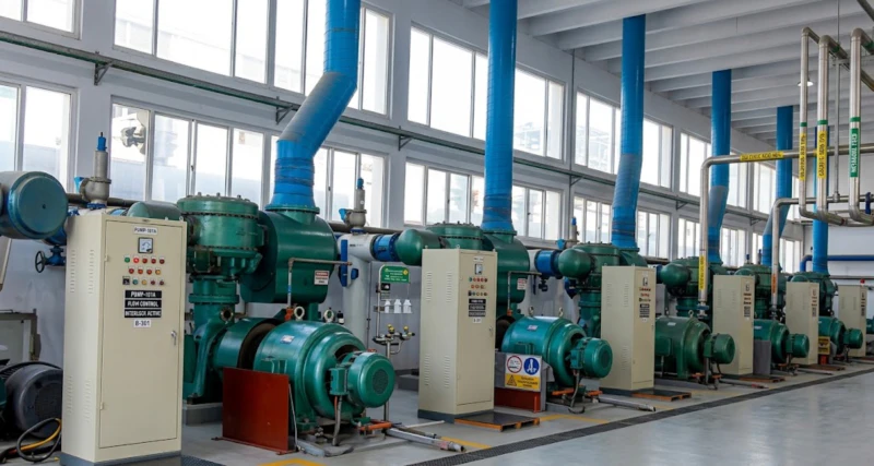
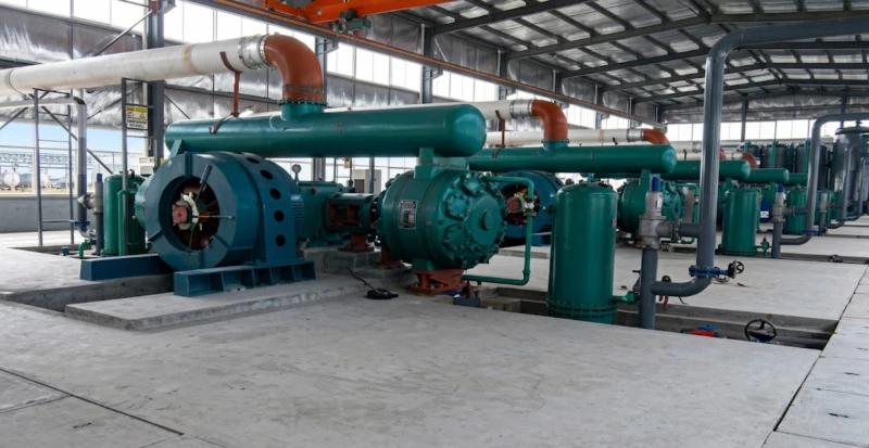
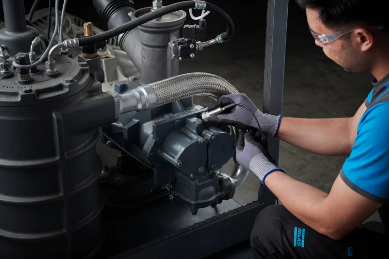
The oil-free reciprocating air compressor series has been installed in fermentation air supply stations across pharmaceutical, food, and industrial bioprocessing facilities. The following images show representative field installations demonstrating typical compressor room layouts, multi-unit parallel station arrangements, and maintenance in progress at customer sites.
How to Choose the Right Oil-Free Compressor Model — Fermentation Sizing Guide
Determine Required Discharge Pressure
The compressor discharge pressure must overcome the sum of: hydrostatic pressure at the sparger depth (0.01 MPa per metre of liquid depth), sparger and diffuser pressure reduction (0.01 to 0.05 MPa for fine-bubble diffusers), pipe distribution pressure loss from compressor to fermenter (0.02 to 0.05 MPa depending on distance and flow rate), and any control valve differential pressure reserve (0.05 MPa minimum). For a typical 5-metre-deep fermenter with fine-bubble spargers, total back-pressure is 0.15 to 0.25 MPa; the compressor discharge pressure should be 0.25 to 0.35 MPa. Add 0.05 MPa margin for pressure fluctuation during batch cycle changes.
Calculate Total Aeration Air Demand
Fermentation aeration rate (VVM — volumes of air per volume of liquid per minute) is typically 0.5 to 1.5 VVM for aerobic fermentation depending on the organism and product. Multiply VVM by total bioreactor working volume to get total volumetric air flow at the fermenter. Convert to free air delivery at atmospheric pressure using: FAD (m³/min) = Fermenter air flow (m³/min) x Absolute discharge pressure (MPa) / 0.1013 MPa. Add 15 to 20% spare capacity margin and allowance for simultaneous demand from multiple fermenters at different batch stages.
Choose Between Single-Stage and Two-Stage Models
For discharge pressures below 0.30 MPa, single-stage LW and DW models provide the best specific energy consumption. For discharge pressures of 0.30 to 0.50 MPa, two-stage models achieve better energy efficiency by splitting the compression ratio across two stages with inter-stage cooling. The crossover point where two-stage becomes more efficient than single-stage is approximately 0.28 to 0.32 MPa under typical ambient conditions. Where discharge pressure requirement is uncertain or may vary between products, two-stage models provide more flexibility to operate at varying output pressures without efficiency penalty.
Plan the Sterilisation Filtration System Downstream
For pharmaceutical fermentation, the oil-free compressed air must still pass through a sterilising-grade inlet air filter (0.2 micron absolute rating for bacteria and mould removal) installed on the fermenter aeration inlet after the after-cooler and moisture separator. Oil-free compressed air does not require oil coalescing or activated-carbon stages. A pre-filter of 1 to 5 micron rating upstream of the sterilising filter extends sterilising filter service life. Filter housings must be steam-sterilisable or disposable for GMP compliance. The compressor manufacturer can provide guidance on filter sizing matched to each compressor model flow rate.
Plan Cooling Water and Foundation Requirements
Oil-free reciprocating compressors require a reliable cooling water supply for cylinder jacket cooling and inter-stage cooling. Cooling water flow rates range from approximately 2 m³/h for small LW models to 30 m³/h for large DW models; detailed requirements are in the installation manual per model. A closed-circuit cooling tower or plate heat exchanger cooling system is standard practice. Foundation requirements follow the same reinforced concrete isolated slab principles as for lubricated reciprocating compressors. Foundation drawings are provided on request at time of order. Anti-vibration mounts between compressor baseplate and concrete foundation are standard.
Oil-Free Reciprocating vs. Oil-Free Screw Compressor — Technical Comparison for Fermentation
Understanding the differences between oil-free reciprocating (piston) and oil-free rotary screw compressors helps buyers choose the optimal technology for fermentation and bioprocessing air supply applications. The comparison below covers the most important technical and commercial factors for fermentation aeration at 0.10 to 0.50 MPa.
| Comparison Item | Oil-Free Reciprocating (This Series) | Oil-Free Screw Compressor |
|---|---|---|
| Oil-free mechanism | PTFE rings + distance piece — intrinsic | Dry rotor coating — relies on coating integrity |
| Maximum single-unit flow | 600 m³/min (HW-600/2.2) | Typically 30 to 60 m³/min per unit |
| Low-pressure efficiency (0.15 to 0.30 MPa) | Optimised single-stage configuration available | Fixed rotor profile less efficient at very low pressure ratios |
| Maintenance complexity | Field-maintainable by plant staff | Rotor replacement needs specialist service team |
| Maintenance event interval | Frequent, low-cost, predictable | Infrequent but high-cost rotor overhaul |
| Oil-free failure mode | No oil source in compression space | Coating failure or bearing damage can release oil |
| Vibration and noise | Higher — foundation design required | Lower — simpler installation |
| Capital cost — large flow (200 m³/min+) | Lower — single large unit vs many small units | Higher — many units required for equivalent flow |
| Typical fermentation application fit | Large-scale pharma, amino acid, industrial bioprocessing | Small to mid-scale labs and food fermentation |
Frequently Asked Questions — Oil-Free Air Compressor for Fermentation
Ready to Specify an Oil-Free Air Compressor for Your Fermentation Project?
Our engineering team provides free fermentation station sizing calculations — including VVM-to-FAD conversion, pressure determination, motor voltage recommendation, foundation load data, and cooling water specifications — for oil-free piston compressor projects of all scales from pilot bioreactor installations to multi-thousand-m³/min industrial fermentation plants. Factory-direct pricing, global export, and full project technical documentation.