
Conventional Power Reciprocating Air Compressor — Two-Stage Twin-Column Series
Piston Reciprocating Compressor for Pneumatic Tools and Industrial Power Utilities · 0.7 to 1.0 MPa · 1.5 to 300 m³/min · 13 to 1800 kW
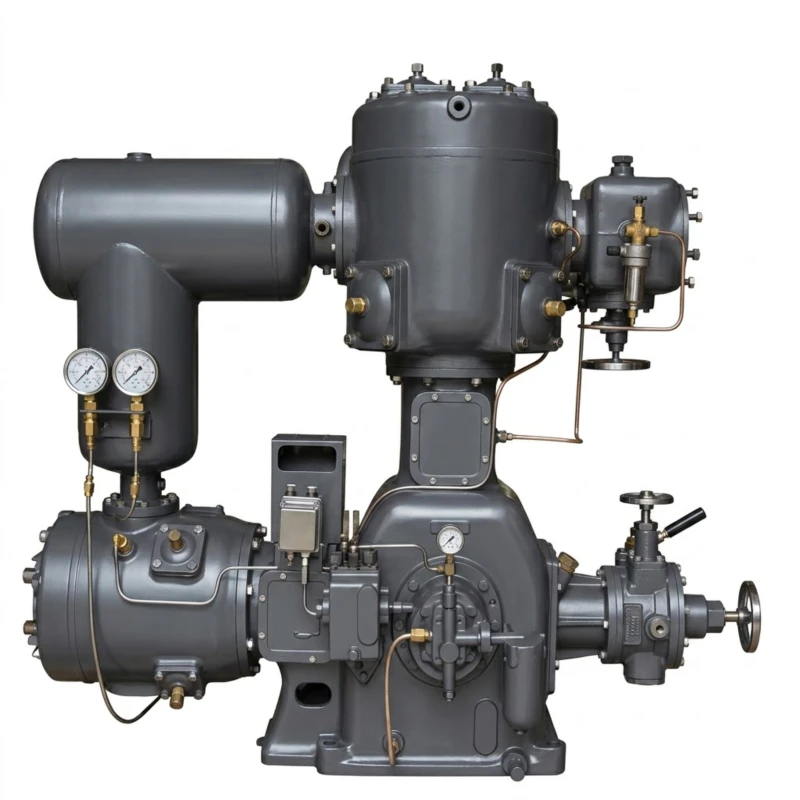
The conventional power reciprocating air compressor is a two-stage piston-type compressed air machine engineered to supply reliable, high-volume compressed air for pneumatic tools, pneumatic equipment, and industrial power utility systems. Available in 48 standard models spanning flow outputs from 1.5 m³/min to 300 m³/min at working pressures of 0.7 MPa, 0.8 MPa, and 1.0 MPa (7 to 10 bar), this series covers the complete range from small workshop installations to large-scale industrial power stations. Drive power ranges from 13 kW to 1,800 kW, with voltage options of 380 V, 6 kV, and 10 kV to suit every grid connection standard.
All standard models use a twin-column two-stage reciprocating compression configuration (W-type or L-type cylinder arrangement), delivering efficient compression with low inter-stage temperature rise and consistent pressure output well suited to the variable demand patterns of pneumatic tool and equipment utility networks. The flagship heavy-duty models HW-200/8 and HW-300/8 adopt a four-column two-stage arrangement providing 200 m³/min and 300 m³/min output respectively for large-scale mining, tunnel construction, and industrial site power supply requirements. All models in the series are also available in an oil-free variant (on request, 11 kW to 2,000 kW range) for applications requiring higher air purity in pneumatic circuits.
Designed for durability in continuous industrial service, the series incorporates robust cast-iron cylinder construction, precision-machined crankshafts, splash-and-pressure combined lubrication systems, and integrated inter-stage cooling for reliable long-life operation. Proven in mining, construction, metallurgy, chemical processing, and heavy manufacturing environments worldwide.
1.5 to 300 m³/min
0.7 / 0.8 / 1.0 MPa
13 to 1800 kW
380 V / 6 kV / 10 kV
48 Standard Models
Oil-Free Version Available
Typical applications: Pneumatic tool supply for construction sites and workshops · Mining and tunnel compressed air utilities · Quarry drilling rigs · Steel mill and foundry pneumatic systems · Petrochemical plant instrument air · Shipbuilding pneumatic lines · Railway maintenance workshops · Municipal water supply pneumatics · Large-scale industrial manufacturing utilities
Technical Parameters — Full Model Range (48 Models)
Model designation key: The number before the slash indicates flow output in m³/min; the number after the slash indicates working pressure in bar (e.g. LW-10/8 = L-type W-arrangement, 10 m³/min at 0.8 MPa). Prefix letters indicate cylinder arrangement type: L = L-type, LW = L-type W-variant, ZW = Z-type W-variant, DW = D-type W-variant, HW = H-type four-column. All standard models are twin-column two-stage unless noted as four-column (HW series).
| No. | Model | Type | Flow (m³/min) | Pressure (MPa) | Dimensions L×W×H (mm) | Weight (t) | Power (kW) | Voltage (V) |
|---|---|---|---|---|---|---|---|---|
| 1 | 1IZA-1.5/8 | Twin-col. single-stage | 1.5 | 0.8 | 700×680×940 | 0.35 | 13 | 380 |
| 2 | ZW-1.5/8 | Twin-col. two-stage | 1.5 | 0.8 | 720×763×1274 | 0.58 | 15 | 380 |
| 3 | 2Z-3/7 | Twin-col. two-stage | 3 | 0.7 | 830×763×1191 | 0.60 | 22 | 380 |
| 4 | ZW-3/7 | Twin-col. two-stage | 3 | 0.7 | 720×763×1475 | 0.80 | 22 | 380 |
| 5 | 2Z-6/8 | Twin-col. two-stage | 6 | 0.8 | 2250×1296×2350 | 2.00 | 45 | 380 |
| 6 | ZW-6/8 | Twin-col. two-stage | 6 | 0.8 | 2250×1296×2350 | 2.00 | 45 | 380 |
| 7 | 3L-10/8 | Twin-col. two-stage | 10 | 0.8 | 1887×910×1781 | 1.70 | 65 | 380 |
| 8 | LW-10/8 | Twin-col. two-stage | 10 | 0.8 | 2340×910×2070 | 1.80 | 65 | 380 |
| 9 | 3L-10/10 | Twin-col. two-stage | 10 | 1.0 | 2340×910×2070 | 1.80 | 75 | 380 |
| 10 | LW-10/10 | Twin-col. two-stage | 10 | 1.0 | 2340×910×2070 | 1.80 | 75 | 380 |
| 11 | ZL3.5-20/8 (no base) | Twin-col. two-stage | 20 | 0.8 | 2142×1731×1982 | 2.20 | 112 | 380 |
| 12 | 4L-20/8 | Twin-col. two-stage | 20 | 0.8 | 2260×1550×1935 | 2.50 | 132 | 380 |
| 13 | LW-20/8 | Twin-col. two-stage | 20 | 0.8 | 2732×1550×2432 | 3.00 | 132 | 380 |
| 14 | 4L-20/10 | Twin-col. two-stage | 20 | 1.0 | 2632×1550×2332 | 3.00 | 132 | 380 |
| 15 | LW-20/10 | Twin-col. two-stage | 20 | 1.0 | 2632×1550×2332 | 3.00 | 132 | 380 |
| 16 | LW-30/8 | Twin-col. two-stage | 30 | 0.8 | 2890×1600×2173 | 4.12 | 200 | 380 |
| 17 | LW-30/10 | Twin-col. two-stage | 30 | 1.0 | 2890×1600×2175 | 4.50 | 220 | 380/6K or 10K |
| 18 | ZL5.5-40/7 (no base) | Twin-col. two-stage | 40 | 0.7 | 2800×1780×2370 | 7.50 | 240 (250) | 380/6K or 10K |
| 19 | L5.5-40/8 | Twin-col. two-stage | 40 | 0.8 | 2890×1600×1880 | 3.70 | 240 (250) | 380/6K or 10K |
| 20 | LW-40/8 | Twin-col. two-stage | 40 | 0.8 | 2890×1600×2173 | 4.12 | 240 (250) | 380/6K or 10K |
| 21 | L5.5-40/10 | Twin-col. two-stage | 40 | 1.0 | 2890×1600×2175 | 4.12 | 260 | 380/6K or 10K |
| 22 | LW-40/10 | Twin-col. two-stage | 40 | 1.0 | 2890×1600×2173 | 4.12 | 260 | 380/6K or 10K |
| 23 | L8-50/8 | Twin-col. two-stage | 50 | 0.8 | 2630×1652×2235 | 6.50 | 315 | 380/6K or 10K |
| 24 | LW-50/8 | Twin-col. two-stage | 50 | 0.8 | 2630×1652×2235 | 6.50 | 315 | 380/6K or 10K |
| 25 | L8-50/10 | Twin-col. two-stage | 50 | 1.0 | 2360×1685×2235 | 6.00 | 315 | 380/6K or 10K |
| 26 | LW-50/10 | Twin-col. two-stage | 50 | 1.0 | 2360×1685×2235 | 6.00 | 315 | 380/6K or 10K |
| 27 | L8-60/8 | Twin-col. two-stage | 60 | 0.8 | 2380×1500×2560 | 6.00 | 350 | 380/6K or 10K |
| 28 | LW-60/8 | Twin-col. two-stage | 60 | 0.8 | 2380×1500×2560 | 6.00 | 350 | 380/6K or 10K |
| 29 | LW-65/7 | Twin-col. two-stage | 65 | 0.7 | 2612×4060×2860 | 6.50 | 400 | 6K or 10K |
| 30 | DW-60/8 | Twin-col. two-stage | 60 | 0.8 | 5000×1800×2500 | 4.00 | 350 | 380/6K or 10K |
| 31 | DW-60/10 | Twin-col. two-stage | 60 | 1.0 | 5496×3558×2575 | 13.00 | 450 | 6K or 10K |
| 32 | DW-75/8 | Twin-col. two-stage | 75 | 0.8 | 5456×3518×2535 | 13.00 | 450 | 6K or 10K |
| 33 | DW-75/10 | Twin-col. two-stage | 75 | 1.0 | 5456×3518×2535 | 13.00 | 480 | 6K or 10K |
| 34 | DW-85/8 | Twin-col. two-stage | 85 | 0.8 | 5456×3518×2535 | 13.00 | 500 | 6K or 10K |
| 35 | DW-85/10 | Twin-col. two-stage | 85 | 1.0 | 5456×3518×2535 | 13.00 | 550 | 6K or 10K |
| 36 | DW-90/8 | Twin-col. two-stage | 90 | 0.8 | 5440×3518×2620 | 13.00 | 550 | 6K or 10K |
| 37 | DW-90/10 | Twin-col. two-stage | 90 | 1.0 | 5440×3518×2620 | 13.00 | 600 | 6K or 10K |
| 38 | 2D12(III)-100/8 | Twin-col. two-stage | 100 | 0.8 | 4622×3353×2535 | 10.50 | 550 | 6K or 10K |
| 39 | DW-100/8 | Twin-col. two-stage | 100 | 0.8 | 5456×3518×2535 | 13.00 | 600 | 6K or 10K |
| 40 | 2D12(III)-100/10 | Twin-col. two-stage | 100 | 1.0 | 4622×3353×2535 | 10.50 | 630 | 6K or 10K |
| 41 | DW-100/10 | Twin-col. two-stage | 100 | 1.0 | 4622×3353×2535 | 10.50 | 630 | 6K or 10K |
| 42 | 2D12(III)-110/8 | Twin-col. two-stage | 110 | 0.8 | 5500×3518×2535 | 13.00 | 630 | 6kV or 10kV |
| 43 | DW-110/8 | Twin-col. two-stage | 110 | 0.8 | 5500×3518×2535 | 13.00 | 630 | 6kV or 10kV |
| 44 | DW-120/7 | Twin-col. two-stage | 120 | 0.7 | 5500×3518×2535 | 13.50 | 650 | 6kV or 10kV |
| 45 | DW-130/8 | Twin-col. two-stage | 130 | 0.8 | 6000×3640×3000 | 18.00 | 800 | 6kV or 10kV |
| 46 | DW-150/8 | Twin-col. two-stage | 150 | 0.8 | 6000×3640×3000 | 19.00 | 900 | 6kV or 10kV |
| 47 | HW-200/8 | Four-col. two-stage | 200 | 0.8 | 5456×6000×2535 | 26.00 | 1200 | 6kV or 10kV |
| 48 | HW-300/8 | Four-col. two-stage | 300 | 0.8 | 6000×8500×3000 | 40.00 | 1800 | 6kV or 10kV |
Note: Custom oil-free (non-lubricated) variants are available to order across the 11 kW to 2,000 kW power range for applications requiring higher air purity. Dimensions are approximate (host assembly only, excluding foundation and auxiliary piping). Weight listed is main host only. Voltage options of 380 V, 6 kV, and 10 kV depend on model size. Contact our technical team for foundation drawings and full installation specifications.
How It Works: Two-Stage Reciprocating Compression Principle
Stage 1 — Low-Pressure Compression
Ambient air is drawn through the inlet filter into the low-pressure (LP) cylinder during the downstroke of the piston. As the piston moves upward, the inlet valve closes and air is compressed from atmospheric pressure (approximately 0.1 MPa) to an intermediate pressure of typically 0.25 to 0.35 MPa. At the top of the stroke, the discharge valve opens and this partially compressed air is pushed through the inter-stage cooler, where it is cooled back toward ambient temperature to improve the volumetric efficiency and reduce the work required for second-stage compression.
Stage 2 — High-Pressure Compression and Delivery
The cooled intermediate-pressure air enters the high-pressure (HP) cylinder, where a second piston compresses it to the final working pressure of 0.7 MPa, 0.8 MPa, or 1.0 MPa as specified. The compressed air passes through the after-cooler and moisture separator before entering the downstream air receiver tank and distribution network. Two-stage compression delivers meaningfully better energy efficiency than single-stage designs at these pressure ratios — typically 10 to 15% lower specific energy consumption per unit volume of compressed air — and produces lower gas temperatures at each stage, extending valve and piston ring service life.
Cylinder Arrangement Types in This Series
The series encompasses three primary cylinder layout configurations. The L-type arrangement places the LP and HP cylinders in an L-shape relative to the crankshaft, providing good balance and compact footprint at medium flow rates. The W-type and Z-type arrangements (LW, ZW, DW series) use a W or Z-shaped multi-cylinder configuration that allows higher flow rates in a balanced, lower-vibration layout suited to larger industrial installations. The four-column H-type arrangement (HW-200/8 and HW-300/8) uses four cylinder columns in a balanced opposing configuration to achieve very large flow outputs of 200 to 300 m³/min while maintaining acceptable foundation vibration levels for permanent plant room installation.
Lubrication System — Splash and Pressure Combined
The crankshaft, connecting rod bearings, and crosshead guides are lubricated by a combined splash and forced-pressure oil lubrication system. An oil pump, driven off the crankshaft, circulates oil under pressure to the main and crankpin bearings. Splash lubrication supplements the cylinder walls and piston rings. The lubrication circuit includes an oil filter and oil cooler on larger models to maintain oil temperature within the design range during extended continuous operation. An optional oil-free piston variant (PTFE piston rings and packing) is available for applications where a small residual oil carry-over from a conventional lubricated model is not acceptable in the air supply.
6 Core Advantages of the Reciprocating Air Compressor Series
Broadest Flow Range in One Series
With 48 standard models covering 1.5 m³/min to 300 m³/min in a single product family, this series eliminates the need to source compressors from multiple suppliers across different project scales. A single technical specification framework, unified spare parts catalogue, and consistent control and instrumentation architecture reduce engineering time for multi-unit installations and simplify long-term maintenance planning.
Two-Stage Efficiency at All Flow Scales
Every model from the smallest ZW-1.5/8 upward uses two-stage compression, providing 10 to 15% lower specific energy consumption per m³ of compressed air delivered compared with single-stage machines at 0.7 to 1.0 MPa. The inter-stage cooling between LP and HP stages reduces compression work and lowers cylinder outlet temperatures, extending valve service intervals and maintaining consistent pressure output over long duty cycles.
Flexible Grid Voltage Options
Models below 200 kW are available at 380 V low voltage, which suits the majority of industrial facilities with standard low-voltage distribution. From 200 kW upward, 6 kV and 10 kV high-voltage motor options are available, enabling direct connection to medium-voltage plant bus-bars without step-down transformers, reducing both capital cost and distribution energy losses for large industrial compressor stations.
Robust Construction for Heavy Industrial Service
Cylinder bodies, cylinder heads, and crankcase housings are cast from high-grade grey or ductile cast iron with large material safety margins. Crankshafts are forged steel, dynamically balanced, and hardened at journal surfaces. Connecting rods and crossheads are precision-machined to close tolerances. This heavy-duty construction is proven over decades of continuous service in mining, steel, and construction environments where ambient conditions are harsh and downtime costs are high.
Field-Serviceable — Low Maintenance Cost
Unlike screw compressors that require specialist tooling and factory service teams for host overhaul, reciprocating compressor maintenance is performed with standard workshop tools by plant maintenance staff. Piston rings, valve plates, valve springs, and piston rod packing are all field-replaceable items stocked as standard spare parts. The open architecture of the crankcase allows visual inspection of all internal moving parts during oil changes without major disassembly.
Oil-Free Variant Available — Same Platform
For applications requiring higher air purity — pharmaceutical packaging, food processing pneumatics, or precision electronics assembly — the same series is available in an oil-free piston variant using PTFE-filled piston rings and distance piece isolation between the crankcase and compression cylinder. This eliminates oil carry-over into the compressed air without the premium cost of a dedicated oil-free screw compressor, covering the 11 kW to 2,000 kW power range on custom order.
Typical Application Scenarios

Mining and Tunnel Construction
Underground mining operations, tunnel boring support, rock drilling jumbos, and shotcrete spraying equipment all rely on large-volume compressed air at 0.7 to 1.0 MPa. The high-flow DW and HW series models (60 to 300 m³/min) supply the simultaneous demand of multiple drilling rigs and utility tools from a single surface compressor station, eliminating the need for multiple smaller units and reducing station footprint and supervision requirements.
Recommended: DW-60/8 to HW-300/8
Quarry Drilling and Stone Processing
Quarry operations require sustained compressed air supply at 0.7 to 0.8 MPa for down-the-hole (DTH) drills, top hammer drills, and pneumatic chain saws. The LW and 4L series (20 to 50 m³/min) provide the flow rate and pressure stability required for efficient rock drilling, with robust cast-iron construction that withstands the dusty, vibration-prone environment of active quarry sites without special protection requirements.
Recommended: 4L-20/8 to L8-50/8
Steel Mills and Foundries
Steel making operations use compressed air for converter lance blowing, ladle stirring, pneumatic slag handling, and control system instrument air. Large foundries use compressed air for core shooting machines, shake-out conveyors, and pattern removal. The DW series (60 to 130 m³/min) at 0.8 MPa suits most steel and foundry utility air station requirements, with 6 kV and 10 kV motor options simplifying connection to the medium-voltage substations typical of heavy metallurgical plants.
Recommended: DW-60/8 to DW-130/8
Pneumatic Tool Supply — Workshops and Construction Sites
Construction sites, shipbuilding yards, railway maintenance depots, and general engineering workshops use compressed air at 0.6 to 0.8 MPa for impact wrenches, grinders, drills, chippers, and riveters. The smaller models in this series (1IZA through LW-10/8, 1.5 to 10 m³/min at 380 V) provide economical, reliable compressed air supply for workshop-scale pneumatic tool networks without the complexity and cost of large industrial compressor installations.
Recommended: 1IZA-1.5/8 to LW-10/10
Chemical and Petrochemical Plants
Process plants require compressed air for pneumatic control valves, instrument air supply, catalyst fluidisation, and mechanical seal flush systems. Continuous, stable compressed air supply at 0.7 to 1.0 MPa is critical for plant safety and control system reliability. The oil-free variant of this series is particularly suited to petrochemical instrument air service where hydrocarbon contamination of the air supply would create process contamination or fire risk.
Recommended: LW-20/8 to DW-100/10 (oil-free variant for instrument air)
Large Industrial Manufacturing Utilities
Automotive assembly plants, heavy equipment manufacturing lines, and large-scale fabrication facilities require centralised compressed air utility stations supplying simultaneous demand from dozens of production tools and assembly fixtures. The mid-range models (LW-30 to DW-90 series, 30 to 90 m³/min) provide the flow capacity for plant-wide utility air distribution at 0.8 MPa, with multiple units arranged in parallel for redundancy and capacity modulation by sequenced loading.
Recommended: LW-30/8 to DW-90/10
Installed at Customer Sites
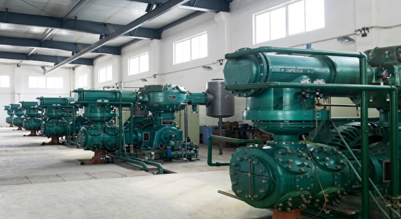
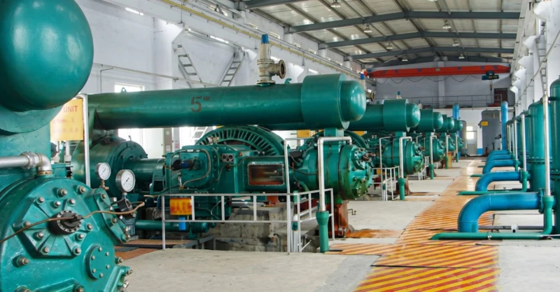
The conventional power reciprocating air compressor series has been installed in compressor stations across mining operations, industrial plants, and infrastructure projects. The following images show representative field installations demonstrating typical installation configurations, foundation arrangements, and multi-unit station layouts.
How to Select the Right Model — Buyer’s Sizing Guide
Determine Required Working Pressure
Most pneumatic tools operate at 0.5 to 0.7 MPa working pressure at the tool inlet. Allow 0.05 to 0.1 MPa for pipe distribution loss. The majority of site pneumatic supply applications are served by 0.8 MPa (8 bar) models. Applications using large-diameter percussion drills or heavy-duty rock breakers may require 1.0 MPa (10 bar). Select the pressure rating one step above your tool inlet requirement to ensure adequate supply pressure across the distribution system under full load.
Calculate Peak Compressed Air Demand
Sum the free air consumption of all pneumatic consumers that may operate simultaneously. Apply a coincidence factor of 0.6 to 0.8 for mixed-tool applications (not all tools run at peak simultaneously). Add 15 to 20% spare capacity for future expansion and to allow the compressor to top up the air receiver efficiently. The result is your required compressor free air delivery (FAD) in m³/min. Select the model whose rated flow output at your chosen pressure meets or exceeds this figure.
Select Voltage Based on Available Grid Supply
Models up to approximately 200 kW are available with 380 V three-phase motors suitable for standard low-voltage supplies commonly found at industrial sites with low-voltage main distribution boards. Models from 200 kW and above, and many models from 100 kW upward, are better suited to 6 kV or 10 kV medium-voltage supply, which is typical of large mining operations, steel plants, and heavy industry facilities with medium-voltage site distribution networks. Confirm your available grid voltage before specifying a model.
Assess Air Purity Requirements
Standard lubricated models are appropriate for the vast majority of pneumatic tool and construction utility applications where small residual oil content in the compressed air is acceptable and commonly present in pneumatic tool exhaust air. Where the compressed air contacts food products, pharmaceuticals, or sensitive electronic assemblies, the oil-free piston variant must be specified. Confirm application air quality requirements against ISO 8573-1 classes before finalising the specification.
Plan Foundation, Ventilation, and Auxiliary Systems
Reciprocating compressors generate higher vibration levels than screw compressors and require designed reinforced concrete foundations with anti-vibration isolation pads. Larger models (DW and HW series) require substantial foundations — engineering drawings are provided with each order. Ventilation must be sufficient to remove cooling air from the after-cooler and maintain ambient temperature below 40 °C in the compressor room. An air receiver tank sized at minimum 10 times the compressor FAD in litres is required for all installations to stabilise system pressure and reduce load cycling frequency.
Reciprocating vs. Screw Compressor — Objective Technical Comparison
Understanding the differences between reciprocating (piston) and rotary screw compressors helps buyers select the right technology for each application. The following comparison covers the most important technical and commercial factors for conventional power utility air supply at 0.7 to 1.0 MPa.
| Comparison Item | Reciprocating (This Series) | Rotary Screw Compressor |
|---|---|---|
| Maximum single-unit flow | 300 m³/min (HW-300/8) | Typically 80 m³/min maximum per standard unit |
| Pressure range covered | 0.7 to 1.0 MPa (this series) | 0.7 to 1.3 MPa typical |
| Energy efficiency at full load | Comparable to screw at full load | Comparable at full load; better at part-load with VFD |
| Energy at part-load (50% demand) | 18 to 25% of rated power (unloaded) | 40 to 55% of rated power (fixed speed unloaded) |
| Maintenance complexity | Field-maintainable by plant staff | Host overhaul typically requires specialist service |
| Vibration and noise | Higher — foundation design required | Lower — simpler installation |
| Maximum single-unit power | 1,800 kW (HW-300/8) | Typically 500 to 900 kW maximum standard model |
| Purchase price per m³/min (large units) | Lower — fewer units needed for large flow | Higher — multiple screw units needed for equivalent flow |
| Oil-free variant available? | Yes — on request, 11 to 2000 kW | Yes — premium price for dry-screw oil-free models |
| Typical application fit | Mining, heavy industry, high-flow utility stations | Variable-demand factory air, general industry |
Frequently Asked Questions — Conventional Power Reciprocating Air Compressor
Ready to Specify a Reciprocating Air Compressor for Your Project?
Our engineering team provides free demand sizing calculations, foundation load data, electrical starting specifications, and total system cost estimates for piston air compressor projects of all scales — from single workshop units to 300 m³/min multi-unit mining station designs. Factory-direct pricing, global export, and full project technical documentation.